4.20.3 Setup of step-up transformer and measurement transformer
If the HV side of the transformer is transforming the voltage up to a voltage level higher than 690 V AC, it will
be necessary with measurement transformers. The setup of all these parameters can be done from the utility
software, and will be explained by an example:
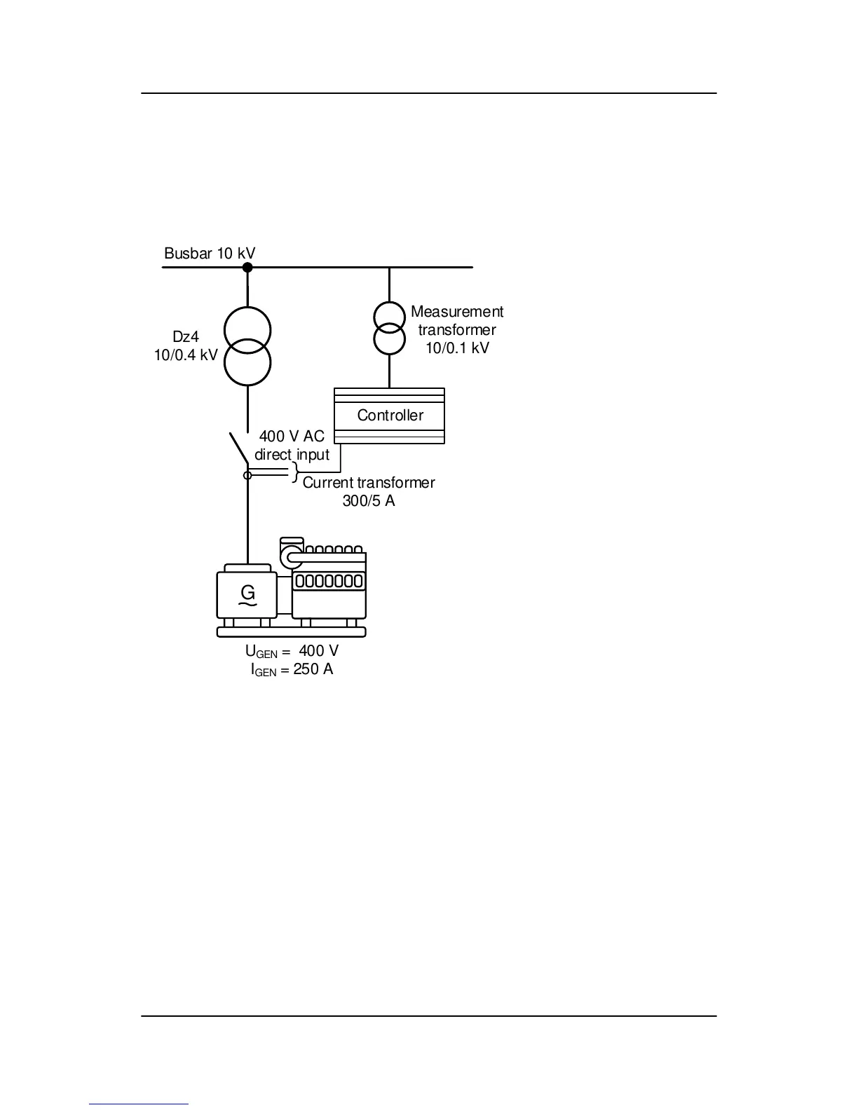
The transformer is a Dz4 step-up transformer, with nominal settings of 10/0.4 kV.
The generator has a nominal voltage of 0.4 kV, nominal current of 250 A, and a nominal power of 140 kW.
The measurement transformer has a nominal voltage of 10/0.1 kV, and no phase angle twist.
The nominal voltage of the busbar (BB) is 10 kV.
Because the generator’s nominal voltage is 400 V, there is no need for a measurement transformer on the LV
side in this example. The ML-2 can handle up to 690 V. But it is still required to set up current transformers on
the LV side. In this example, the current transformers have a nominal current of 300/5 A.
Due to the fact that the step-up transformer is a Dz4, there will be a phase angle twist of -120 °.
These settings can be programmed via the display or the utility software. These settings must be put into the
parameters shown in the table below:
GPC-3 DRH 4189340587 UK
Additional functions
DEIF A/S Page 89 of 122

 Loading...


