M-Logic is used to execute different commands at predefined conditions. M-Logic is not a PLC but substitutes
one, if only very simple commands are needed.
M-Logic is a simple tool based on logic events. One or more input conditions are defined, and at the activa-
tion of those inputs, the defined output will occur. A great variety of inputs can be selected, such as digital
inputs, alarm conditions and running conditions. A variety of the outputs can also be selected, such as relay
outputs, change of genset modes and change of running modes.
The M-Logic is part of the PC utility software, and as such it can only be configured in the PC
utility software and not via the display.
The main purpose of M-Logic is to give the operator/designer more flexible possibilities of operating the gen-
erator control system.
Refer to the document “ML-2 application notes M-Logic” for a description of this configuration
tool.
The manual governor and AVR control function can be activated by pressing more than two seconds,
or by activating the digital inputs or AOP buttons for governor or AVR control in semi-auto mode. The inten-
tion of this function is to give the commissioning engineer a helpful tool for adjustment of the regulation.
When using the display arrows for increasing or decreasing, the output will change as long as the button is
active. For the digital input and AOP buttons, there is a timer so that it is possible to choose how long one
pulse should be; the timer can be set to 0.1 to 10 sec. For the governor, the timer parameter is 2782 and for
AVR, it is 2784. If for example the timer is set to 5 sec., then one push on the AOP or one pulse from digital
input will give 5 sec. increase or decrease of the output.
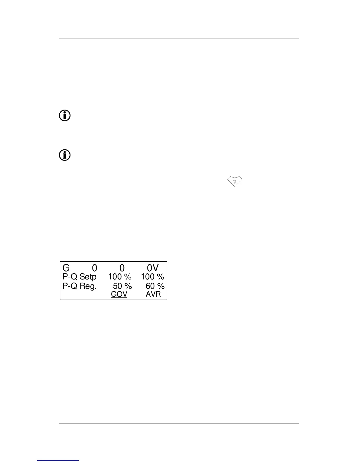
The function of the regulation window depends on the selected mode:
4.16 Mode configuration
4.16.1 Manual mode
In manual mode the regulation is deactivated. When activating the up or down arrows, the output value to
GOV or AVR is changed, this is the Reg. value in the display. The up and down arrows have the same func-
tion as the digital inputs or AOP buttons for governor and AVR control when the window is open. To exit the
regulation window press "back".
Local/remote mode
As in manual mode, the up and down arrows have the same function as the digital inputs or AOP buttons for
governor or AVR control when the window is open.
GPC-3 DRH 4189340587 UK
Additional functions
DEIF A/S Page 71 of 122

 Loading...


