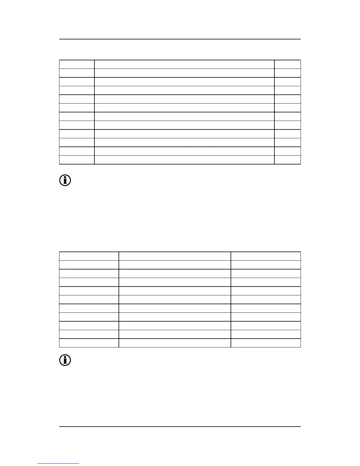
Parameter Comment Setting
6002 Generator nominal power 140
6003 Generator nominal current 250
6004 Generator nominal voltage 400
6041 LV measurement transformer primary side (There is none here) 400
6042 LV measurement transformer secondary side (There is none here) 400
6043 Current transformer primary side 300
6044 Current transformer secondary side 5
6051 HV (BB) measurement transformer primary side 10000
6052 HV (BB) measurement transformer secondary side 100
6053 Nominal HV setting of step-up transformer 10000
9141 Phase angle compensation 120 °
The ML-2 controller can directly handle voltage levels between 100 and 690 V. If the voltage lev-
el in the application is higher or lower, it is required to use measurement transformers that
transform the voltage into a number between 100 and 690 V.
4.20.4 Vector group for step-down transformer
In some applications, there may also be a step-down transformer. This could be to transform a grid voltage
down, so the load can handle the voltage level. The ML-2 controller is able to synchronise the busbar with the
mains, even if there is a step-down transformer with a phase angle twist. The transformer must be between
the measuring points for ML-2. If a step-down transformer is used, these settings will must be set in parame-
ter 9141 to compensate the phase angle twist.
Vector group Step-up transformer types Parameter 9141
0 Yy0, Dd0, Dz0 0 °
1 Yd1, Dy1, Yz1 -30 °
2 Dd2, Dz2 -60 °
4 Dd4, Dz4 -120 °
5 Yd5, Dy5, Yz5 -150 °
6 Yy6, Dd6, Dz6 180 °
7 Yd7, Dy7, Yz7 150 °
8 Dd8, Dz8 120 °
10 Dd10, Dz10 60 °
11 Yd11, Dy11, Yz11 30 °
If a step-down transformer is mounted with an ML-2 genset unit, the settings shown in the table
above should also be used.
GPC-3 DRH 4189340587 UK Additional functions
DEIF A/S Page 90 of 122

 Loading...


