EasyManuals Logo

Deif GPC-3 Designers Reference Handbook

Deif GPC-3
122 pages
To Next Page IconTo Next Page
To Previous Page IconTo Previous Page
Page #26 background imageLoading...
Page #26 background image
USW 3 setup:
DU-2 setup:
G 0 0 0V
1170 G U< 1
Relay 5
SP DEL OA OB ENA FC
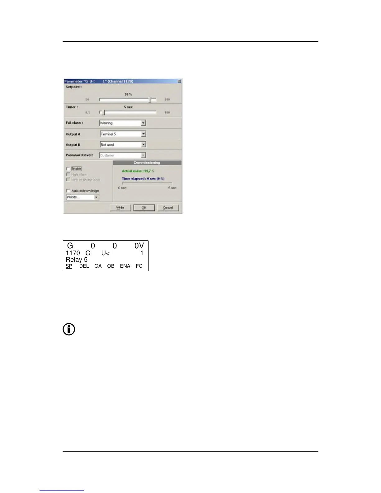
SP = set point. DEL= timer. OA = output A. OB = output B. ENA = enable. FC = fail class.
Alarm display
All enabled alarms will be shown in the display, unless the output A as well as the output B are adjusted to a
“limit” relay.
If output A and output B are adjusted to a limit relay, then the alarm message will not appear
but the limit relay will activate at a given condition.
Definitions
There are three states for an enabled alarm.
GPC-3 DRH 4189340587 UK Additional functions
DEIF A/S Page 26 of 122

Table of Contents

Other manuals for Deif GPC-3

Questions and Answers:

Question and Answer IconNeed help?

Do you have a question about the Deif GPC-3 and is the answer not in the manual?

Deif GPC-3 Specifications

General IconGeneral
BrandDeif
ModelGPC-3
CategoryController
LanguageEnglish

Related product manuals