EasyManuals Logo

Deif GPC-3 Designers Reference Handbook

Deif GPC-3
122 pages
To Next Page IconTo Next Page
To Previous Page IconTo Previous Page
Page #87 background imageLoading...
Page #87 background image
Connections:
1L1
1L2
1L3
Generator
2L1
2L2
2L3
AGC 3/ AGC 4/ PPU/
GPU/ PPM/ GPC
AGC 200
79
61
81
63
83
65
85
68
87
70
89
72
Busbar
GB
LV HV
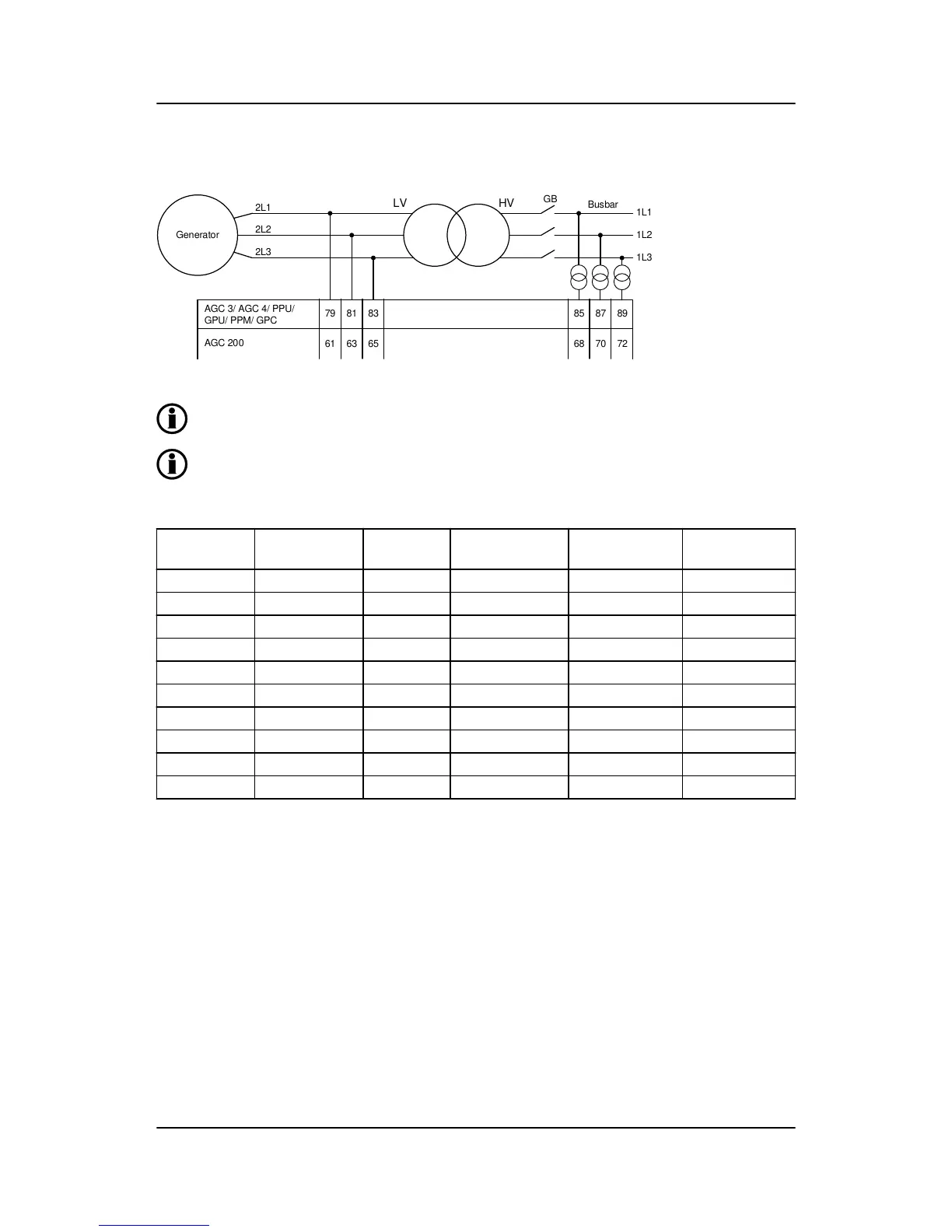
The connection shown in the diagram should always be used when an ML-2 is used for a gen-
set.
Select 179 degrees in parameter 9141 when vector group 6 is used.
Comparison table between different terminologies:
Vector group Clock notation Phase shift LV lag degrees
compared to HV
LV side lagging LV side leading
0 0 0 ° 0 ° 0 °
1 1 -30 ° 30 ° 30 °
2 2 -60 ° 60 ° 60 °
4 4 -120 ° 120 ° 120 °
5 5 -150 ° 150 ° 150 °
6 6 -180 °/180 ° 180 ° 180 ° 180 °
7 7 150 ° 210 ° 150 °
8 8 120 ° 240 ° 120 °
10 10 60 ° 300 ° 60 °
11 11 30 ° 330 ° 30 °
In the following, the name vector group will be used.
GPC-3 DRH 4189340587 UK Additional functions
DEIF A/S Page 87 of 122

Table of Contents

Other manuals for Deif GPC-3

Questions and Answers:

Question and Answer IconNeed help?

Do you have a question about the Deif GPC-3 and is the answer not in the manual?

Deif GPC-3 Specifications

General IconGeneral
BrandDeif
ModelGPC-3
CategoryController
LanguageEnglish

Related product manuals