The numbered front-end switch ports used for connecting to the ports on the EX500 nodes are
shown in the following diagram. Port 1 on the Hare switch (FE2) connects to port 4 on Node 1.
Port 2 on the Hare switch (FE2) connects to port 4 on Node 2, and so on. Similarly, Port 1 on the
Rabbit switch (FE1) connects to port 3 on Node 1. Port 2 on the Rabbit switch (FE1) connects to
port 3 on Node 2, and so on.
Figure 21 Node ports on front-end switches
Rabbit Switch (FE1)
Hare Switch (FE2)
1
48 46 44 42 40 38 36 34 32 30
28 26 24 22 20 18 16 14 12 10 8 4 6 2
3 5 7 9 11 13 15 17 19 21 23 25
27
29 35
31
33 37
39 41
43 45 47
VLT1
VLT2
1
48 46 44 42 40 38 36 34 32 30 28 26 24 22 20 18 16 14 12 10 8 4 6 2
3 5 7 9 11 13 15 17 19 21 23 25
27
29 35
31
33 37
39 41
43 45 47
VLT1
VLT2
customer ports
51
52
52
51
53
53
54
54
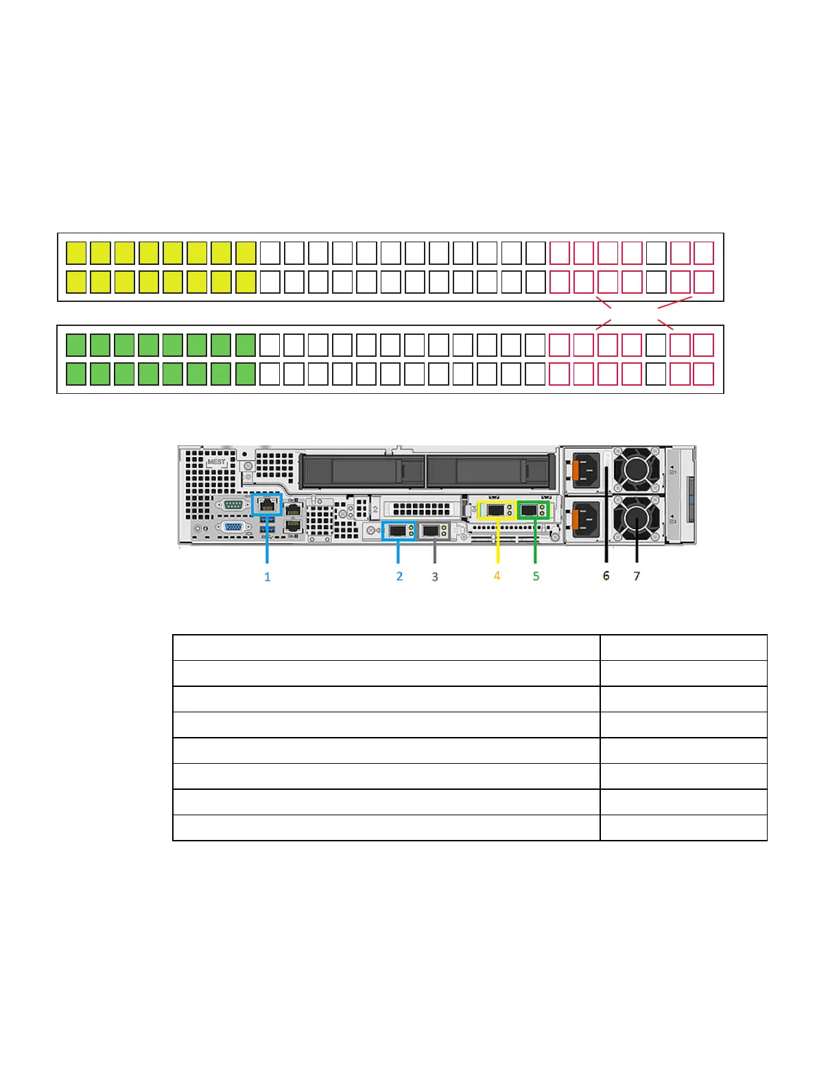
Figure 22 Network cable and labeling
In the table below,
x
is the server number.
Network Cable Description
Labeling
1 - iDRAC management port, back-end switch 1 Server
x
iDRAC *
2 - Back-end switch 1 Server
x
BE 1 *
3 - Back-end switch 2 Server
x
BE 2 *
4 - Front-end switch 2 Server
x
FE 2 *
5 - Front-end switch 1 Server
x
FE 1 *
6 - Power cable (black) AC PS1
7 - Power cable (grey) AC PS2
The numbered back-end switch ports used for connecting to the ports on the EX500 nodes are
shown in the following diagram. Port 1 on the Hound switch (BE2) connects to port 2 on Node 1.
Port 2 on the Hound switch (BE2) connects to port 2 on Node 2, and so on. Similarly, Port 1 on the
Fox switch (BE1) connects to port 1 on Node 1. Port 2 on the Fox switch (BE1) connects to port 1
on Node 2, and so on.
EX500 Platform
ECS EXSeries Hardware Guide 45
 Loading...