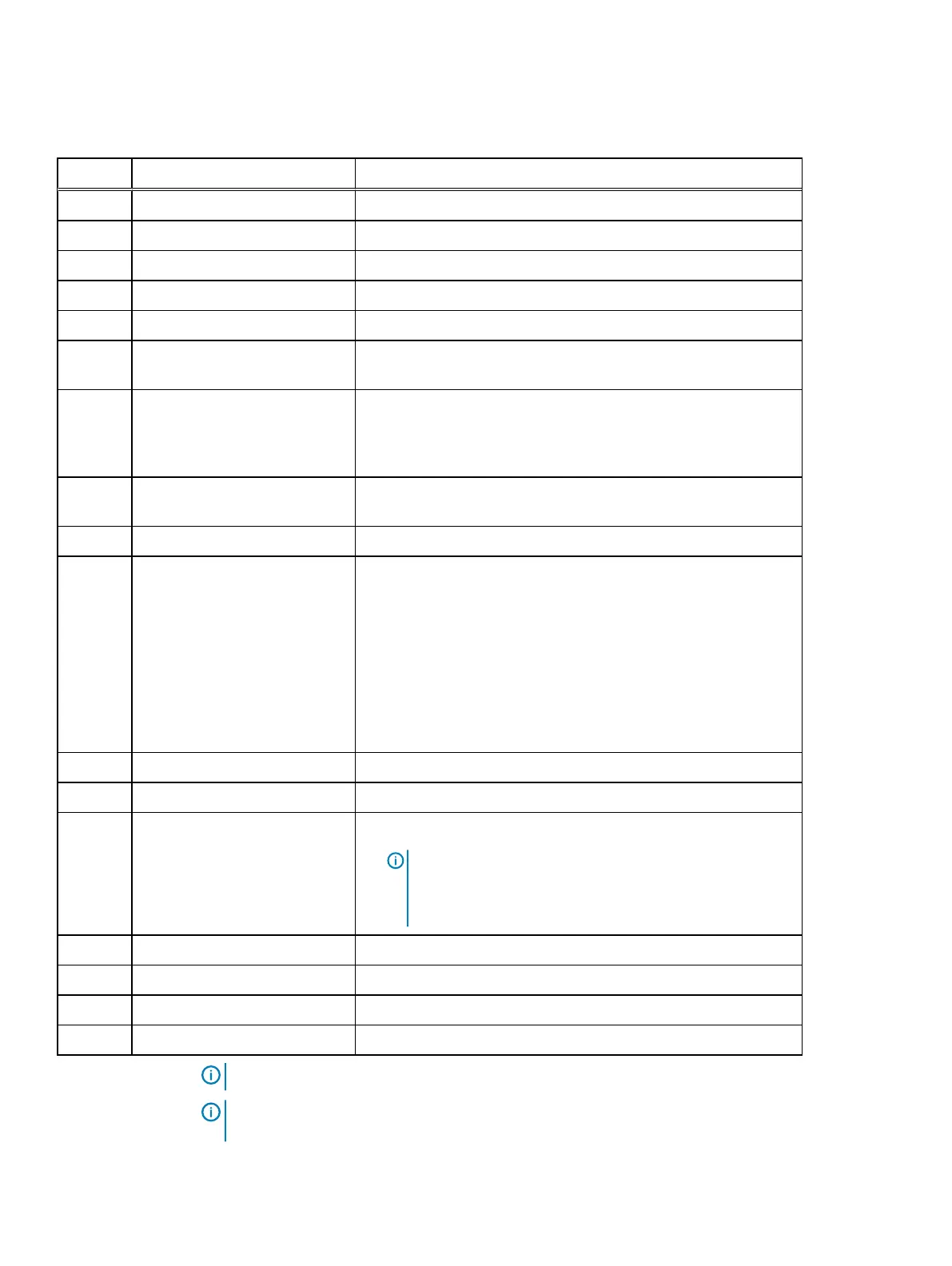
Table 28 Server indicators, buttons, or connectors
Item Indicator, Button, or Connector Description
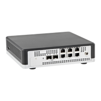
1 Blade EN connector (optional) This function is reserved.
2 Serial connector Enables you to connect a serial device to the system.
3 Video connector Enables you to connect a VGA display to the system.
4 Ethernet connector 1 Integrated 10/100/1000 Mbps NIC connector.
5 Ethernet connector 2 Integrated 10/100/1000 Mbps NIC connector.
6 USB connector Enables you to connect USB devices to the system. The port is USB
2.0-compliant.
7 SD vFlash card slot Provides persistent on-demand local storage and a custom
deployment environment that allows automation of server
configuration, scripts and imaging. For more information, see the
Integrated Dell Remote Access Controller 9 (iDRAC9) User’s Guide.
8 USB connector Enables you to connect USB devices to the system. The port is USB
3.0-compliant.
9 Dedicated Ethernet port Dedicated management port on the iDRAC ports card.
10 System identification button
l
The identification button can be used to locate a particular
system within a rack.
l
Press to toggle the system ID on and off.
l
If the system stops responding during POST, press and hold the
system ID button for more than five seconds to enter BIOS
progress mode.
l
To reset iDRAC (if not disabled in F2 iDRAC setup) press and
hold the button for more than 15 seconds.
11 Ethernet connector 3 Integrated 10/100/1000 Mbps NIC connector.
12 Ethernet connector 4 Integrated 10/100/1000 Mbps NIC connector.
13 Power button
l
The power button controls the PSU output to the system.
l
Note: On ACPI-compliant operating systems (OSs), turning
off the system using the power button causes the system to
perform a graceful shutdown before power to the system is
turned off.
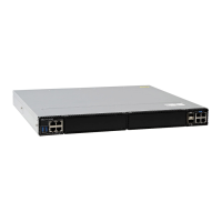
14 Boot HDD A 2.5-inch boot HDD
15 Boot HDD B 2.5-inch boot HDD
16 Power supply units Two redundant power supply units (PSUs) for sled A.
17 Power supply units Two redundant power supply units (PSUs) for sled B.
Note: Features of sled B are for EX3000D dual-node systems only.
Note: A dummy sled (sled B) will be installed over the sled A compartment and two dummy
PSUs over the PSU slots for sled B in the EX3000S single-node system.
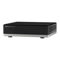
EX3000 Platform
ECS EXSeries Hardware Guide 99
 Loading...