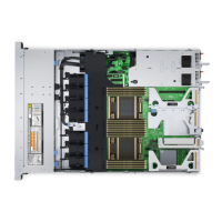
Item Connector Description
8. RGT_CP_CONN Right panel connector
9. SYS_PWR_CONN(P1) System power connector
10. J_PIB_SIG1 Power interface board signal connector 1
11. J_PIB_SIG2 Power interface board signal connector 2
12. J_ACE Internal Dual SD Module
13. J_CP_USB2 Front USB connector
14. J_SATA_A1 Internal SATA A connector
15. J_SATA_C1 Internal SATA C connector
16. PCIE_G3_X8(CPU1) Internal PERC controller connector
17. J_REAR_BP_PWR1 ODD power connector
18. J_FRONT_VIDEO VGA connector
19. INT_USB_3.0 USB connector
20. NVRAM_CLR Clear NVRAM
21. PWRD_EN Reset BIOS password
22. SLOT6 PCIe slot 6
23. SLOT5 PCIe slot 5
24. SLOT4 PCIe slot 4
25. J_TPM_MODULE TPM module connector
26. J_BP_SIG0 Backplane signal connector
27. J_MEZZ_A1 LOM riser card connector
28. BATTERY Battery connector
29. PCIE_G3_X16(CPU1) Riser 1 connector
30. A6, A5, A10, A4, A9, A7, A1, A8, A2, A3 Memory module sockets
31. B3, B2, B1, B4, B5, B6 Memory module sockets
32. CPU2 Processor socket 2
33. PCIE_A0 NVMe connector
34. CPU2_PWR_CONN(P3) CPU2 power connector
System board jumper settings
For information on resetting the password jumper to disable a password, see the Disabling a forgotten password section.
174
Jumpers and connectors
 Loading...

