Processor fan and heat-sink assembly
Removing the processor fan and heat-sink assembly
CAUTION: The information in this section is intended for authorized service technicians only.
Prerequisites
1. Follow the procedure in Before working inside your computer.
2. Remove the side cover.
3. Remove the front bezel.
4. Remove the 3.5-inch hard drive, if applicable.
5. Remove the disk-drive cage.
About this task
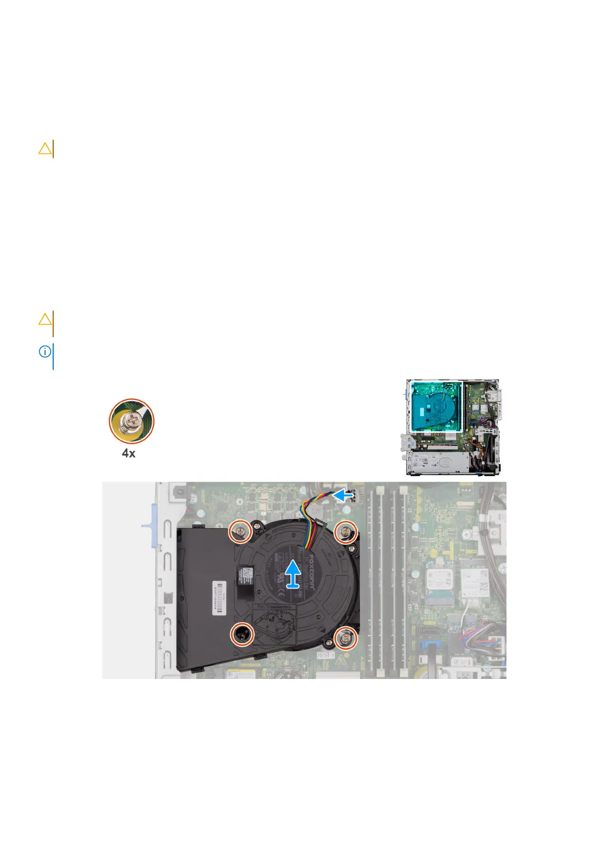
The following images indicate the location of the processor fan and heat-sink assembly and provide a visual representation of
the removal procedure.
CAUTION: For maximum cooling of the processor, do not touch the heat transfer areas on the heat sink. The oils
in your skin can reduce the heat transfer capability of the thermal grease.
NOTE: The heat sink may become hot during normal operation. Allow sufficient time for the heat sink to cool before you
touch it.
Figure 50. Removing the processor-fan and heat-sink assembly
Steps
1. Disconnect the processor-fan cable from its connector (FAN CPU) on the system board.
2. In the reverse sequential order (4>3>2>1), loosen the four captive screws that secure the processor fan and heat-sink
assembly to the system board.
3. Lift the processor fan and heat-sink assembly off the system board.
Removing and installing Field Replaceable Units (FRUs)
93