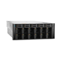
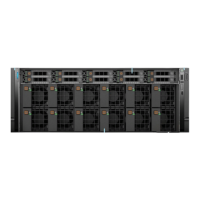
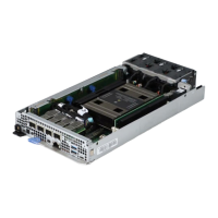
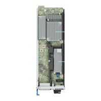
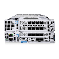
LAAC GPU Dip tray
Removing the LAAC GPU Dip tray
Prerequisites
1. Follow the safety guidelines listed in the Safety instructions.
2. Follow the procedure listed in the Before working inside your system.
3. Remove the air shroud.
4. Remove the front top cover.
5. Remove the cooling fan and fan cage assembly.
6. Remove the expansion card risers.
7. Remove the memory modules.
8. Remove the heat sink.
9. Remove the processors.
10. Remove the OCP card (if installed).
11. Remove the power supply units (PSU).
12. Remove the VSB
13. Disconnect cables that are connected to the components.
14. Remove the system board
15. Remove the system board tray.
Steps
1. Using a Phillips 2 screwdriver, loosen the two blue thumb screws on both side of the GPU assembly.
2. Hold the two blue thumb screws and rotate the GPU assembly toward rear of the system.
3. Lift the black latch and disconnect the GPU cable connecting on the NVlink baseboard.
Figure 113. Removing the GPU assembly and cable
4. Observe and disconnect the cables from the LAAC GPU Dip Tray connector from the PDB and backplane.
5. Unlock the two blue thumb screws on the LAAC GPU Dip tray and two blue thumb screws on the LAAC Radiator handles.
Rotate both the handles at an angle. Holding both the handles, lift GPU with LAAC assembly away from the chassis.
Installing and removing system components
137

 Loading...
