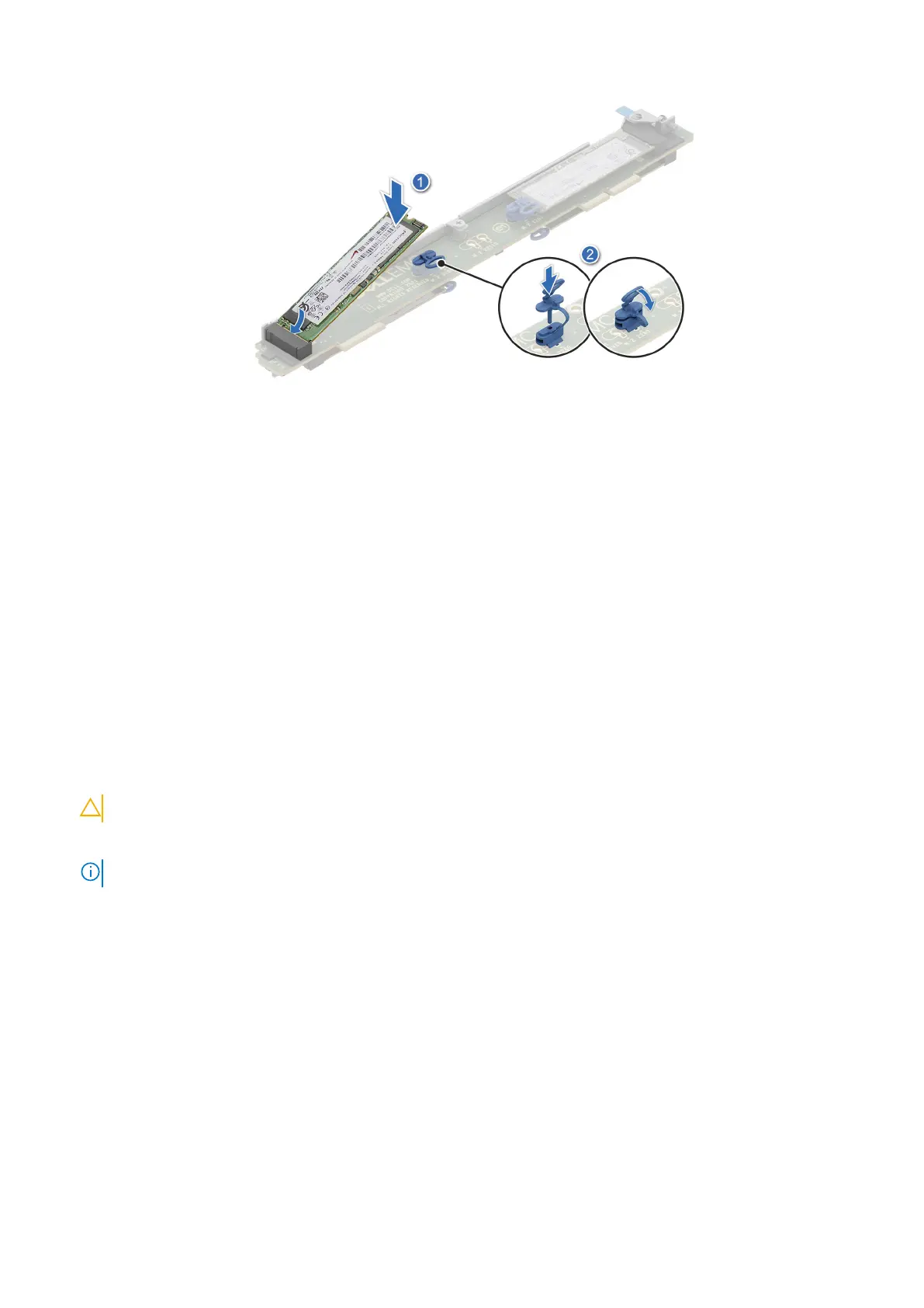
Figure 31. Installing the M.2 SSD module
Next steps
1. Installing the M.2 riser module.
2. Follow the procedure listed in the After working inside your system.
Network I/O board
Removing the Network I/O board
Prerequisites
1. Follow the safety guidelines listed in Safety instructions.
2. Follow the procedure listed in Before working inside your system.
Steps
1. Using the Phillips 2 screwdriver, loosen the blue thumbscrew.
CAUTION: Follow the guiding pin to prevent damage to the Network I/O board.
2. Disconnect the Network I/O board signal cable connected on the system board.
NOTE: Observe the routing of the cable as you remove it from the system.
3. Disconnect the Network LED RAF or NAF signal cable from the Network I/O board. To disengage the Network I/O board
from the slots on the chassis, slide the Network I/O board towards the rear of the system.
66
Installing and removing system components

 Loading...


