c. Memory modules
d. M.2 BOSS card
e. M.2 Riser card
f. Network I/O Board
g. Disconnect all cables from the system board.
CAUTION: Take care not to damage the system identification button while removing the system board
from the system.
Steps
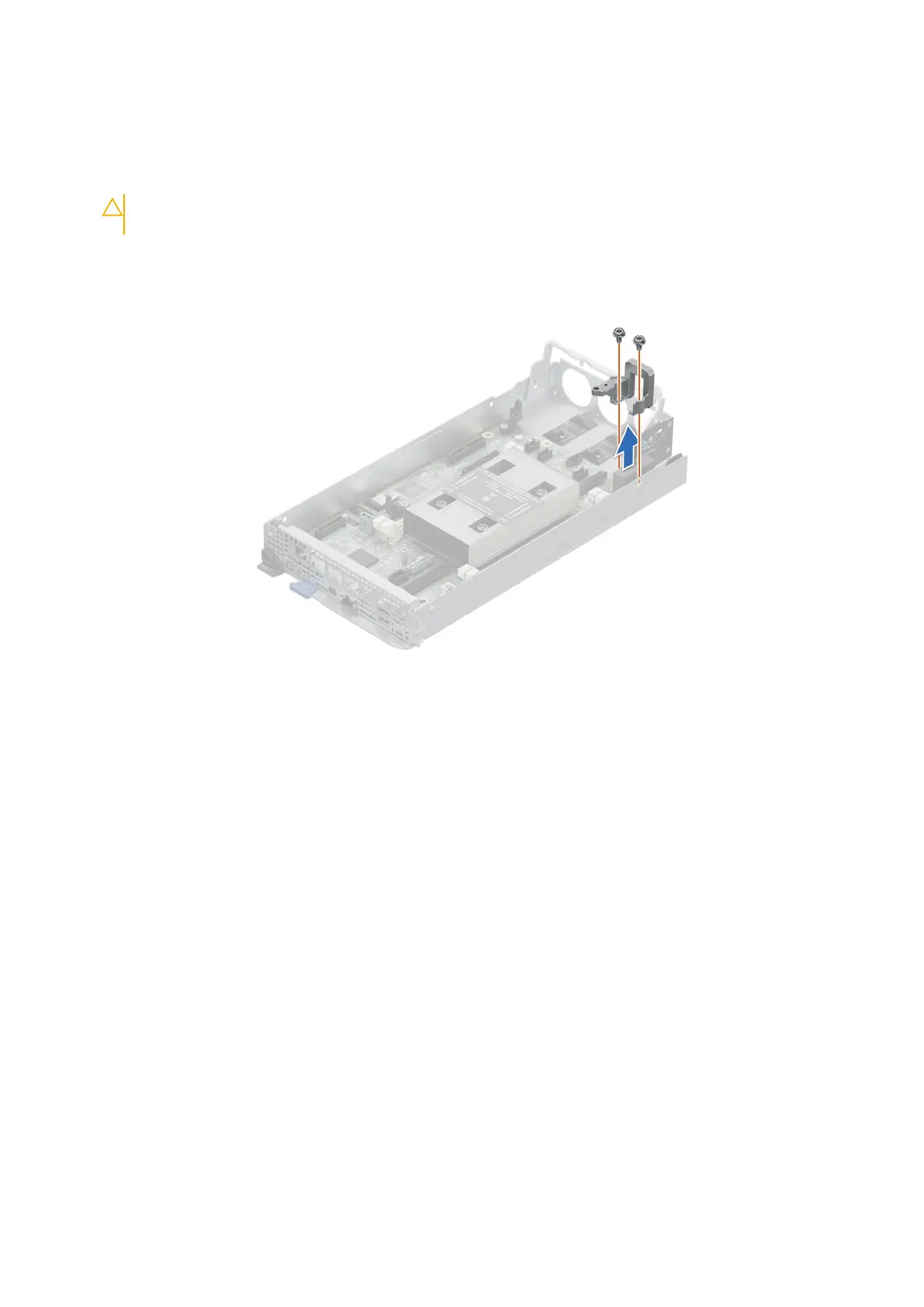
1. Using a Phillips 2 screwdriver, remove the two screws that secure the connector cover on the system board to the chassis.
Figure 37. Removing the connector cover
2. Using a Phillips 2 screwdriver, remove the five screws that secure the system board to the chassis.
3. To disengage the ports from the slots on the chassis, slide the system board toward the rear of the chassis. Lift the system
board out of the chassis.
Installing and removing system components
71

 Loading...


