EasyManuals Logo

Dell PowerEdge XR4510c User Manual

Dell PowerEdge XR4510c
86 pages
To Next Page IconTo Next Page
To Previous Page IconTo Previous Page
Page #73 background imageLoading...
Page #73 background image
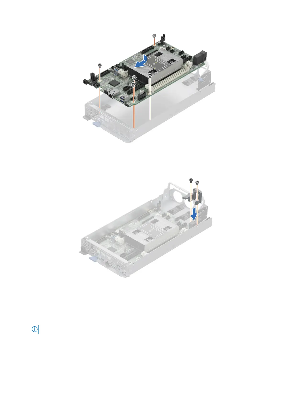
Figure 39. Installing the system board
5. Using a Phillips 2 screwdriver, tighten the screws that secure the connector cover to the system board.
Figure 40. Installing the connector cover
Next steps
1. Replace the following components:
a. Trusted platform module (TPM).
NOTE: The TPM Module must be replaced only while installing new system board.
b. Memory modules
c. M.2 BOSS card
d. M.2 riser card
e. M.2 SSD
f. Cooling fans
Installing and removing system components
73

Table of Contents

Questions and Answers:

Question and Answer IconNeed help?

Do you have a question about the Dell PowerEdge XR4510c and is the answer not in the manual?

Dell PowerEdge XR4510c Specifications

General IconGeneral
BrandDell
ModelPowerEdge XR4510c
CategoryServer
LanguageEnglish

Related product manuals