5. Connect the power button board with fingerprint reader FPC to the system board.
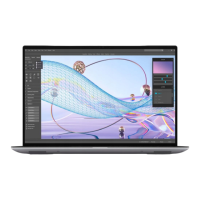
6. Connect the USH board FPC (for models shipped with a USH board) and touchpad FPC to their respective connectors.
7. Connect the battery LED FPC to the system board.
8. Route the WLAN antenna cables using the metal clips on the system board and connect them to the WLAN module.
9. Tighten the single (M1.6x2.3) captive screw to secure the WLAN bracket on the system board.
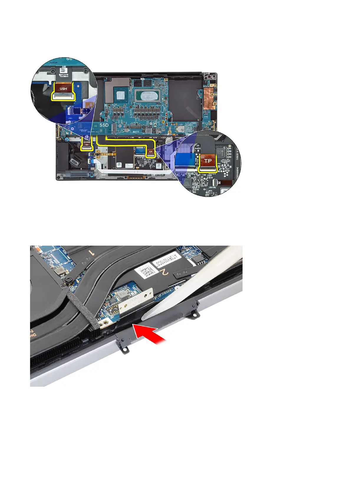
10. Use a plastic scribe to tuck the display FPC into the gap between the system board and the bottom assembly until the white
line on the display connector lines up with the edge of the system board.
Removing and installing components
55