Chapter 6 Applied Instructions
6-75
API
Instruction code Operand Function
0201 D BIN P
S, D
Converting the binary-coded
decimal number into the binary
Device
X Y M S T C HC D L SM SR E PR K 16# “$” DF
Pulse instruction 16-bit instruction (5 steps)
32-bit instruction (5 steps)
AH500 AH500 AH500
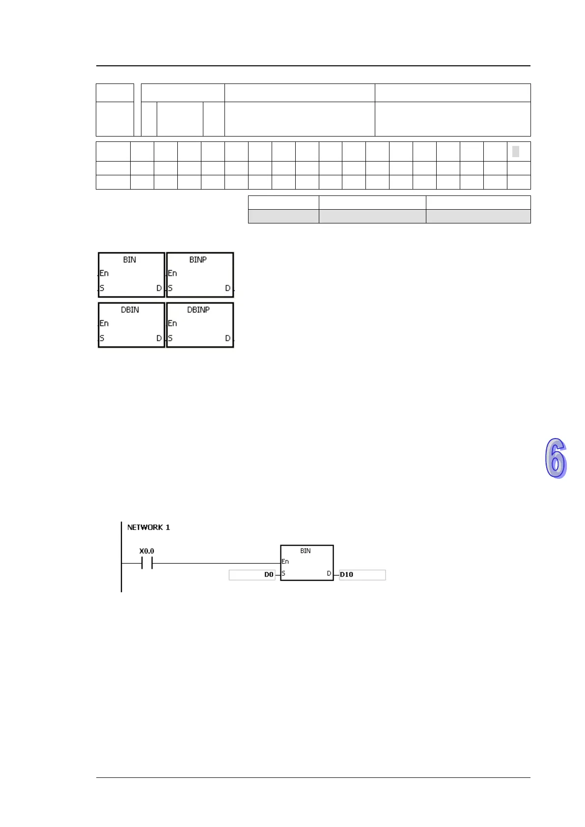
Symbol:
S
:
Source device Word/Double word
D
:
Conversion result Word/Double word
Explanation:
1. The binary-coded decimal value in S is converted into the binary value, and the conversion
result is stored in D.
2. The 16-bit binary-coded decimal value in S should be within the range between 0 and 9,999,
and the 32-bit binary-coded decimal value in S should be within the range between 0 and
99,999,999.
3. Only the 32-bit instructions can use the 32-bit counter.
4. Constants and hexadecimal values are converted into binary values automatically. Therefore,
users do not need to use the instruction.
Example:
When X0.0 is ON, the binary-coded decimal value in D0 is converted into the binary value, and the
conversion result is stored in D10.
Additional remark:
1. If the value in S is not the binary-coded decimal value, the operation error occurs, SM0 is ON,
and the error code in SR0 is 16#200D (The binary-coded decimal value is represented by the
hexadecimal value, but one of digits is not within the range between 0 and 9.).
2. The application of the instructions BCD and BIN:
Before the value of the binary-coded decimal type of DIP switch is read into the PLC,
users have to use the instruction BIN to convert the data into the binary value and store
the conversion result in the PLC.
If users want to display the data stored inside the PLC in a seven-segment display of the
binary-coded decimal type, they have to use the instruction BCD to convert the data into
the binary-coded decimal value before the data is sent to the seven-segment display.
When X1.0 is ON, the binary-coded decimal value in X0.0~X0.15 is converted into the

 Loading...


