Chapter 6 Applied Instructions
6-279
API
Instruction code Operand Function
1209 CCD P
S, D, n
Sum check
Device
X Y M S T C HC D L SM SR E PR K 16#
“$” DF
16-bit instruction (7 steps)
Symbol:
S
:
Initial device Word
D
:
Device in which the sum is
stored
Word
n
:
Number of pieces of data Word
Explanation:
1. In communication, the sum check is used to compare checksums on the same data on
different occasions or on different representations of the data in order to verify the data
integrity.
2. The 16-bit conversion mode: When SM606 is OFF, the working mode of the instruction is the
16-bit conversion mode. The n pieces of data in the registers starting from the register
specified by S (eight bits as a group) are added up. The sum is stored in the register specified
by D, and the values of the parity bits are stored in D+1.
3. The 8-bit conversion mode: When SM606 is ON, the working mode of the instruction is the
8-bit conversion mode. The n pieces of data in the registers starting from the register specified
by S (Eight bits forms a group, and only low eight bits are valid.) are added up. The sum is
stored in the register specified by D, and the values of the parity bits are stored in D+1.
4. The operand n should be within the range between 1 and 256.
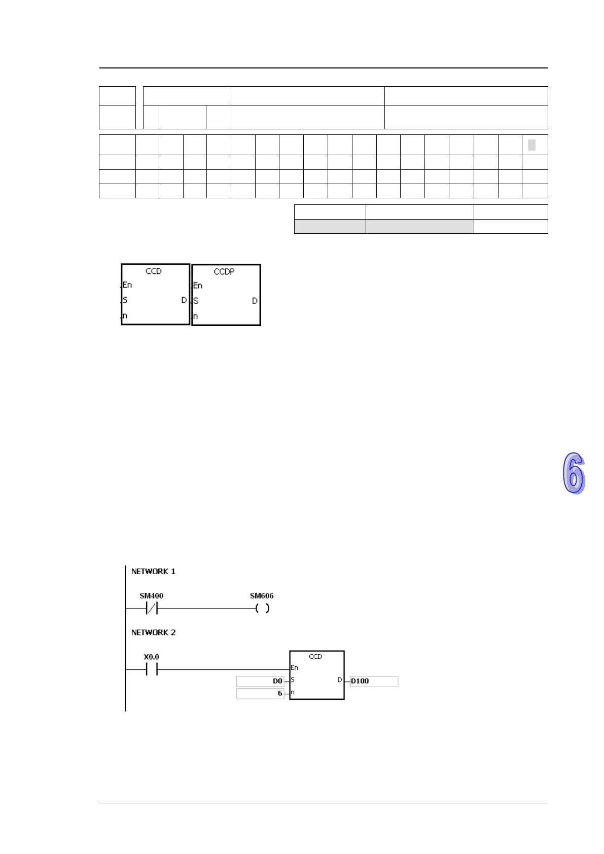
Example 1:
1. When SM606 is OFF, the working mode of the instruction is the 16-bit conversion mode.
2. When X0.0 is ON, the six pieces of data in D0~D2 (eight bits as a group) are added up. The
sum is stored in D100, and the values of the parity bits are stored in D101.

 Loading...


