AH500 Programming Manual
6-280
D100
D101
0 0 0 0 0 0 0 0 001 1 1 1 1 1
0 0 0 0 0 0 0 0 0 0 0 00 1 10
S
Data
D0 Low
D0 High
D1 Low
D1 High
D2 Low
D2 High
D100
D101
100 = 0 1 1 0 0 1 0 0
111 = 0 1 1 0 1 1 1 1
120 = 0 1 1 1 1 0 0 0
202 = 1 1 0 0 1 0 1 0
123 = 0 1 1 1 1 0 1 1
211 = 1 1 0 1 0 0 1 1
0 0 0 1 0 0 0 1
The parity bit is set to 1 if the number of ones is odd.
The parity bit is set to 0 if the number of ones is even.
867
Sum
Parity bits
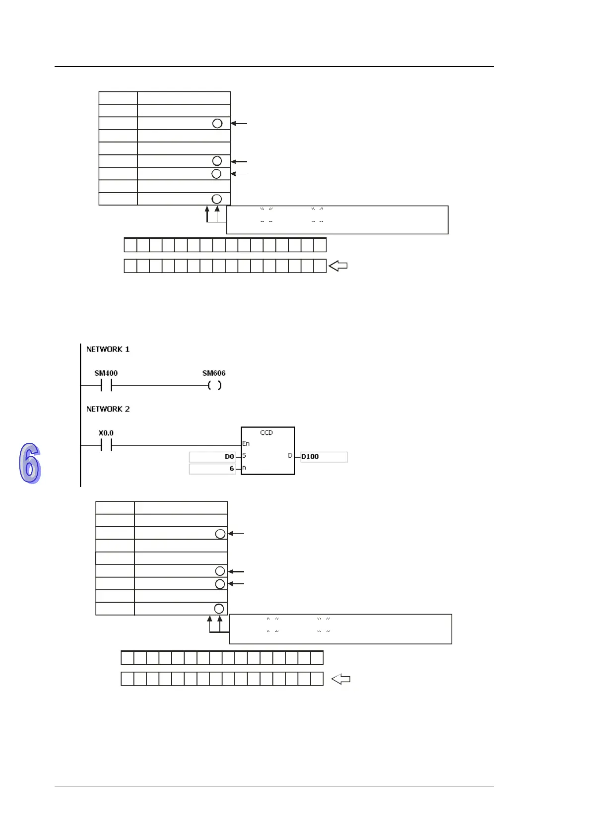
Example 2:
1. When SM606 is ON, the working mode of the instruction is the 8-bit conversion mode.
2. When X0.0 is ON, the six pieces of data in D0~D5 (eight bits as a group) are added up. The
sum is stored in D100, and the values of the parity bits are stored in D101.
Data
The parity bit is set to 1 if the number of ones is odd.
The parity bit is set to 0 if the number of ones is even.
Sum
Parity bits
D100
D101
0 0 0 0 0 0 0 0 001 1 1 1 1 1
0 0 0 0 0 0 0 0 0 0 0 00 1 10
S
D0 Low
D1 Low
D2 Low
D3 Low
D4 Low
D5 Low
D100
D101
100 = 0 1 1 0 0 1 0 0
111 = 0 1 1 0 1 1 1 1
120 = 0 1 1 1 1 0 0 0
202 = 1 1 0 0 1 0 1 0
123 = 0 1 1 1 1 0 1 1
211 = 1 1 0 1 0 0 1 1
0 0 0 1 0 0 0 1
867
Additional remark:
1. Suppose SM606 is ON. If S+n-1 exceeds the device range, the instruction is not executed,
SM0 is ON, and the error code in SR0 is 16#2003.
2. Suppose SM606 is OFF. If S+n/2-1 exceeds the device range, the instruction is not executed,
SM0 is ON, and the error code in SR0 is 16#2003.

 Loading...


