AH500 Programming Manual
6-414
The PLC sends the data.
Low 8 bits
16#01 Address
Low 8 bits
16#06 Function
Low 8 bits
16#20
Data address
Low 8 bits
16#00
16#00
Data
16#12
16#02 CRC CHK 0
16#07 CRC CHK 1
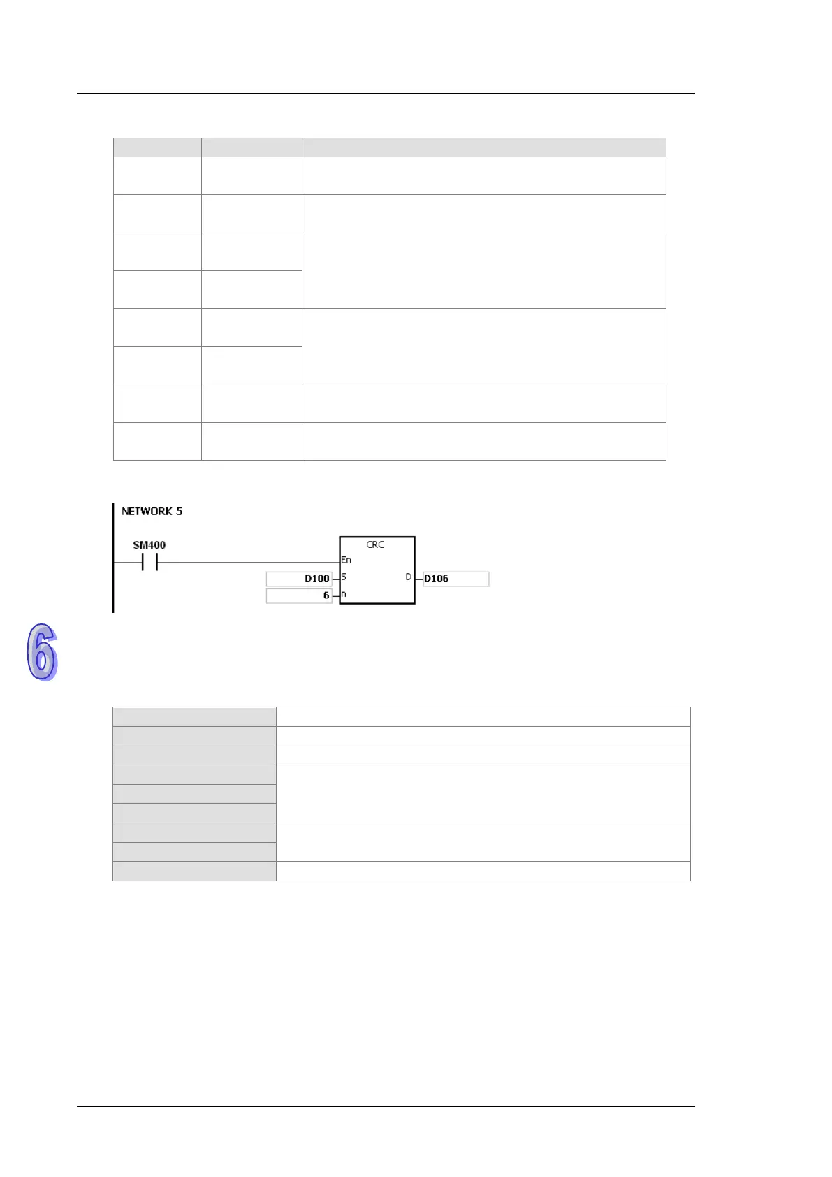
CRC CHK (01) above is the error checking code. It can be calculated by means of the
instruction CRC. (8-bit mode: SM606 is ON.)
CRC check code: 16#02 is stored in the low 8-bit in D106, and 16#07 is stored in the low 8-bit
in D107.
Additional remark:
1. The format of the communication data in the RTU mode:
Communication address: 8-bit binary address
Function code: 8-bit binary code
Data: n×8-bit data
The 16-bit check code is composed of two 8-bit binary codes.
2. CRC check code: The check code starts from the address to the data. The operation rule is as
follows.
Suppose the data in the 16-bit register (the register in which the CRC check code is
stored) is 16#FFFF.
The logical operator XOR takes the first 8-bit message and the low 8-bit data in the
16-bit register, and performs the logical exclusive OR operation on each pair of
corresponding bits. The operation result is stored in the 16-bit register.
The values of the bits in the 16-bit registers are shifted by one bit to the right. The
value of the highest bit becomes 0.

 Loading...


