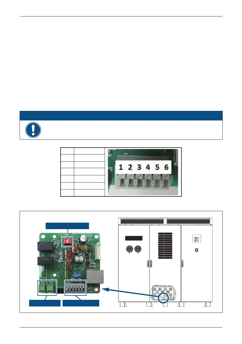
The Communication Module provide the function of communication with 2-port
RS-485 and 2-port dry contacts.
4.8 Connection of Communication Modules
The pin definition of RS-485 is shown as in Table 4-1. Installer should switch ON
the terminal resistor when single inverter is installed. The cable wire position and
wiring of multi-inverter connection is shown as Figure 4-15 & Figure 4-16.
Installer must switch ON terminal resister at the first and last devices on the
RS-485 chain as Figure 4-15. The other terminal resisters must be switch OFF.
Please refer to Table 4-3 for the terminal resister setting.
4.8.1 RS-485 Connection
PIN
1
2
Function
VCC(+12V)
GND
3
4
5
6
DATA+
DATA
-
DATA+
DATA
-
Table 4-1 : Definition of RS-485 PIN
Figure 4-17 : Cable Wire Position for Multi-inverter Connection
Dry Contact RS-485 & VCC
In order to have good transfer quality, twisted-pair wire is recommended to be
used as communication cable.
ATTENTION
Terminal Resistor
44
Installation