5-39
5
ௐ
ௐ
Installation and Wiring
2
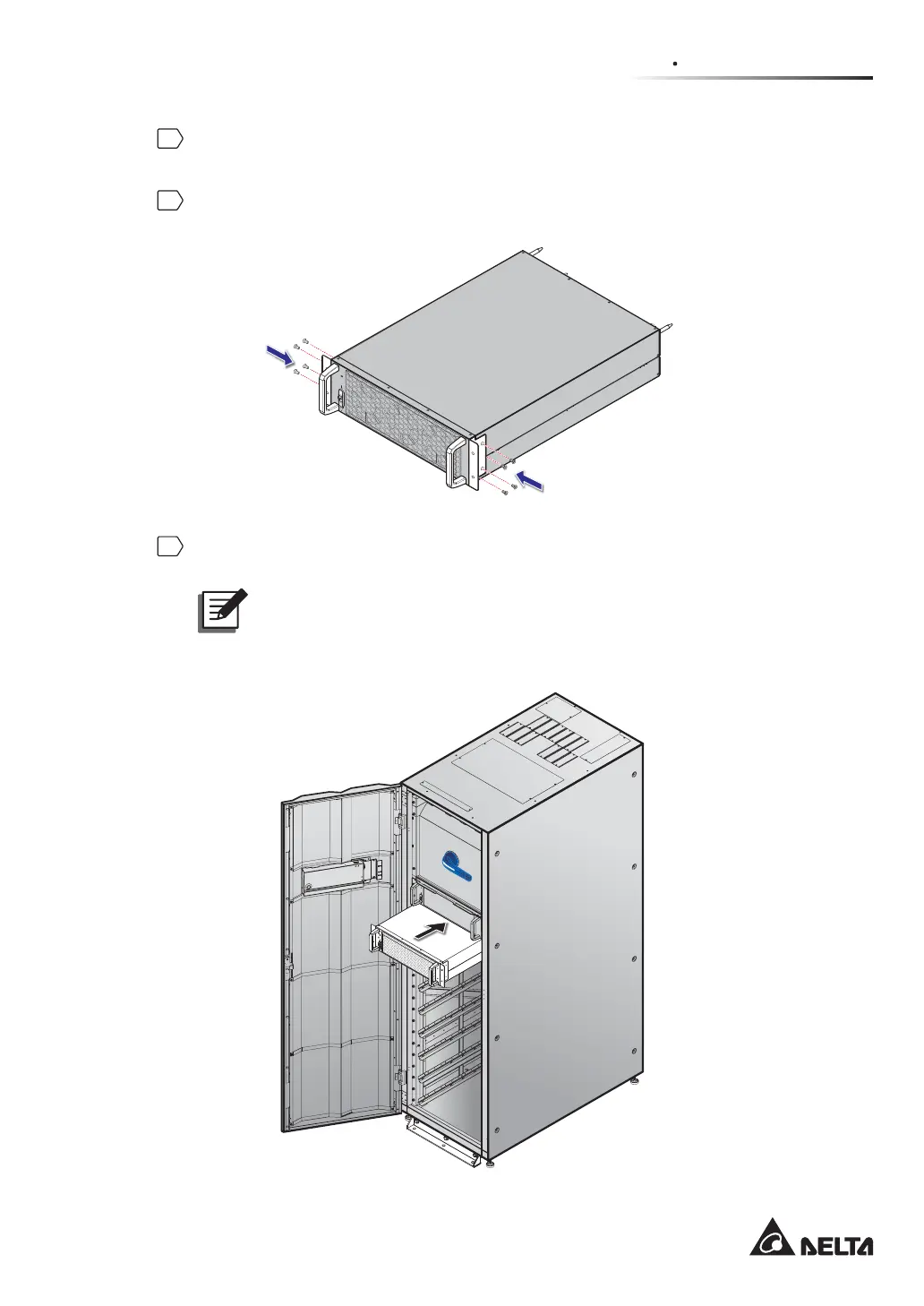
Take out the two bracket ears, four M6 screws and eight M4 screws from the power
module’s package.
3
Use the provided eight M4 screws to fix the provided two bracket ears on the two sides
of the power module. Please refer to Figure 5-39.
(Figure 5-39: Install the Two Bracket Ears)
4
Insert the power module into the power module slot until it snaps into place. Two people
are required.
127(To consider the center of gravity, please install the power modules
from the top layer of the power module slot to the bottom layer of the power
module slot in sequence.
M
OD
B
U
S
B
M
S
G
ND
B
A
G
N
D
B
A
DISPLAY
EMS
ICONSOLE
RESET
ON I
BYPASS SWITCH
(UPS Front View with Door Open)
(Figure 5-40: Insert the Power Module into the UPS)
 Loading...