2-8
Modulon DPH Series
2.6 Internal View
WARNING:
Only authorized Delta engineers or service personnel can perform installation,
wiring, panel & cover removal, maintenance and operation. If you want to execute
any action mentioned above by yourself, the action must be under the supervision
of authorized Delta engineers or service personnel.
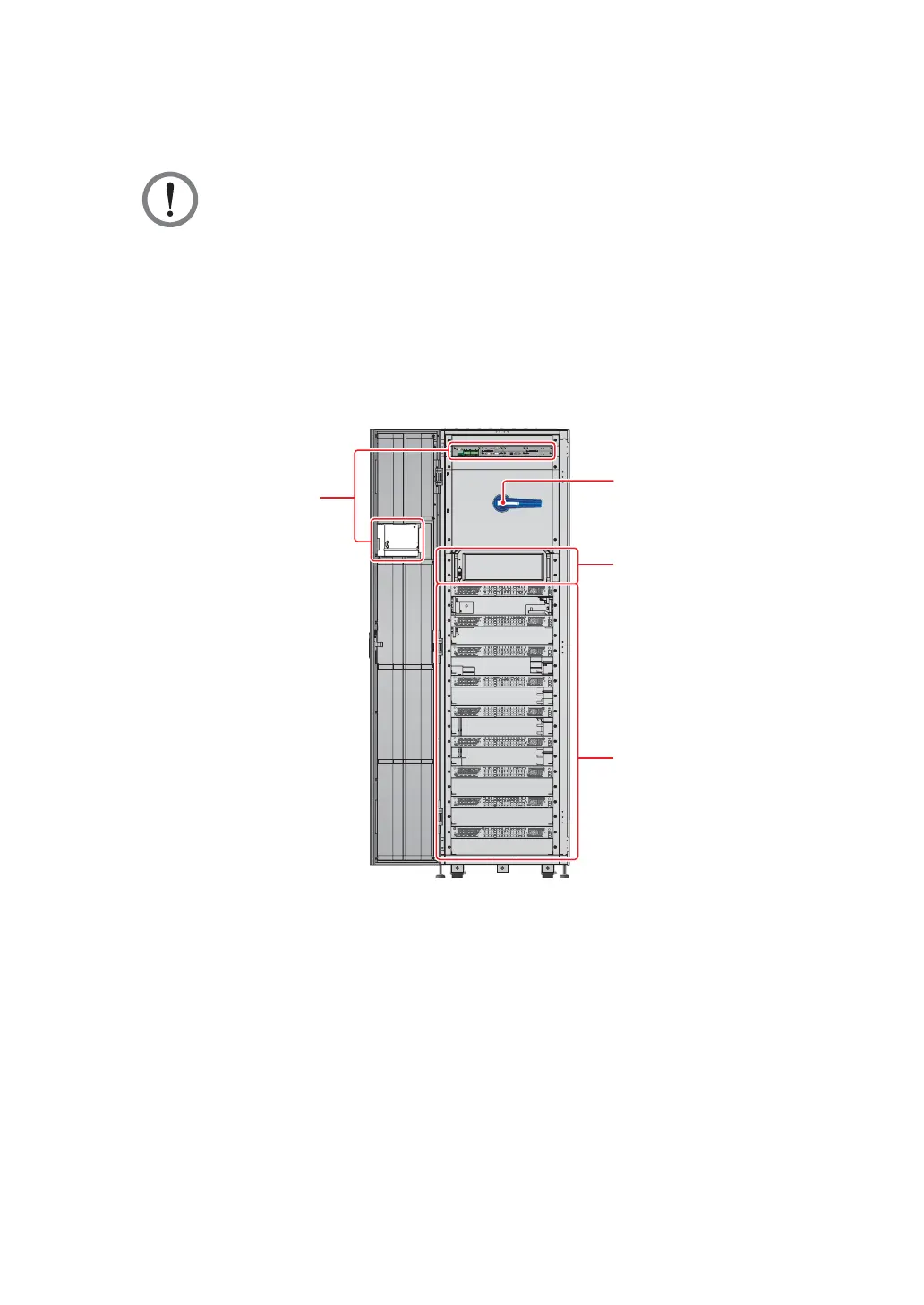
After you open the UPS’s front door, you will see the internal mechanisms including
communication interfaces, a bypass switch (Q0), an STS module, and nine power module
slots. Please refer to Figure 2-4.
M
OD
B
US
BM
S
G
N
D
B
A
G
N
D
B
A
D
ISP
L
A
Y
EMS
I
C
ONS
O
LE
DISPLAY
REPO
NCNO
EXT. BATT
TEMP.
BT1 BT2
EXT.SWITCH
STATUS
S1 S2
S3 S4
BT3
BT4
O/P DRY
CONTACT
USB RS-232
P1 P2 P3
P4
P5 P6
I/P DRY
CONTACT
P1 P2
BATT.
START
BATT.
START
P3
P4
PARALLEL
PARALLEL
O OFF
ON I
RESET
BYPASS SWITCH
Bypass Switch (Q0)
Communication Interfaces
STS Module
Power Module Slots
Internal View
(Front View with Door Open)
(Figure 2-4: UPS Internal View (Front View with Door Open))
1. For information about the communication interfaces, please refer to 4. Communication
Interfaces.
2. For how to turn on/ off the bypass switch (Q0), please refer to Figure 2-5.
 Loading...