6-30
Modulon DPH Series
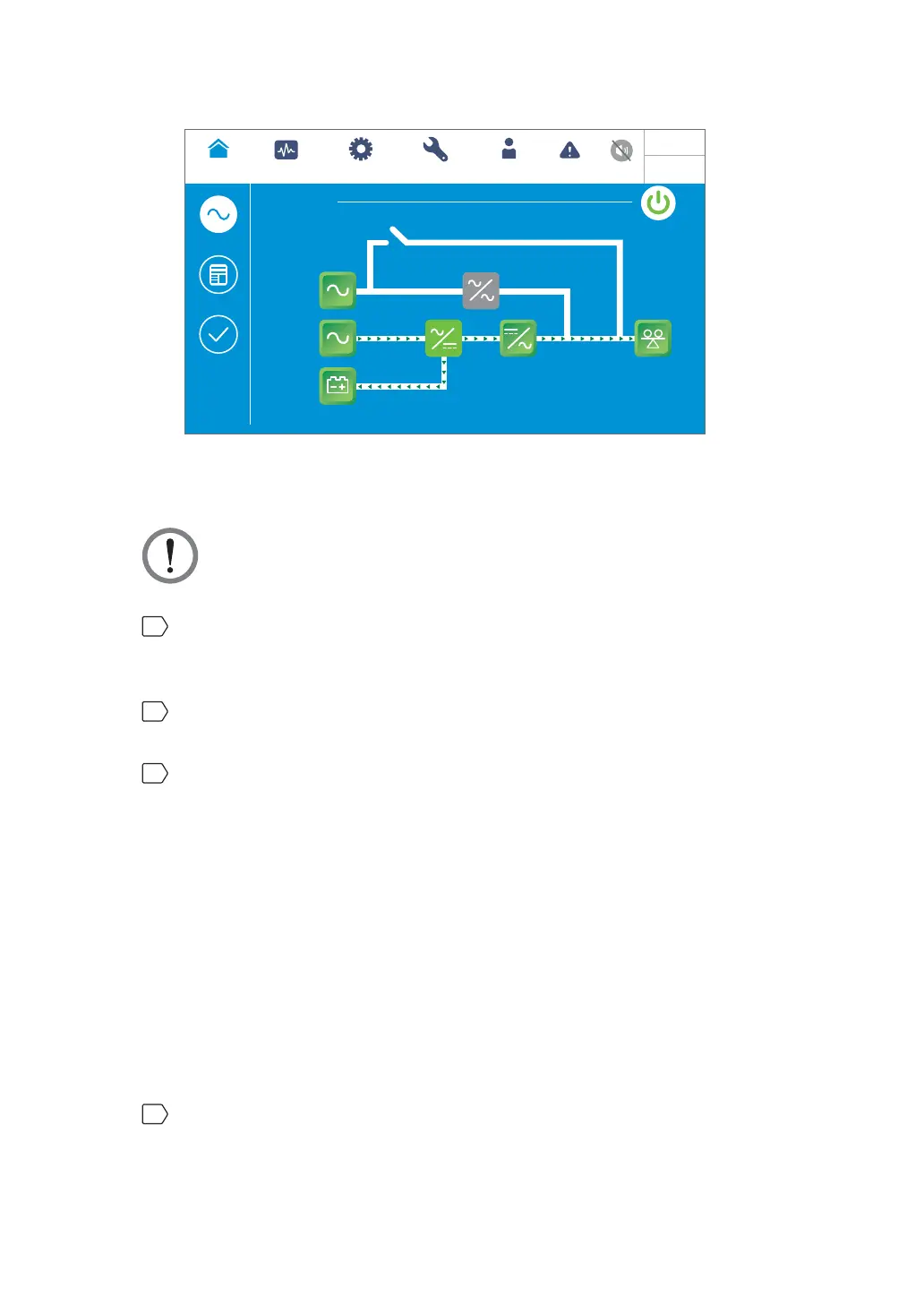
Green
POWER FLOW
Maintenance
Bypass
Bypass
Mains
90 %
5 mins
Load
30 %
MEASUREMENT
Power Flow
UPS-1.1 SETUP
MAINTENANCE EVENT LOG
Power Flow
Summary
System Status
LOG IN
Administrator
10:15
May 25,2018
(Figure 6-38: Green Mode Screen)
6.2.8 Energy Recycle Mode Start-up Procedures
WARNING: Energy recycle mode is only applicable to single input and single unit
application.
1
Ensure that the Delta or non-Delta external maintenance bypass cabinet’s manual
bypass breaker or switch (Q3), output breaker or switch (Q4) and every external battery
cabinet’s breaker (Q5) are in the OFF position.
2
Switch ON the bypass switch (Q0) of the UPS and the input breaker or switch (Q1) of
the Delta or non-Delta external maintenance bypass cabinet.
3
After you switch ON the UPS’s bypass switch (Q0) and the Delta or non-Delta external
maintenance bypass cabinet’s input breaker or switch (Q1), each auxiliary power card’s
LED indicator will illuminate green and the following status will occur simultaneously.
1. The system and each power module will start initialization. After each power module
finishes initialization, each power module’s fans will start running, each power module
will start establishing DC BUS voltage and each power module’s LED indicator will
illuminate green.
2. Each parallel communication card’s LED indicator will illuminate red first and then
each parallel communication card will start initialization. After initialization, the
master parallel communication card’s LED indicator will illuminate green and the
backup communication card’s LED indicator will illuminate yellow.
For the locations of parallel communication cards, auxiliary power cards, power modules
and associated LED indicators, please refer to Figure 6-1.
4
The LCD initial screen (see Figure 6-39) will appear within 40 seconds after the UPS’s
bypass switch (Q0) and the Delta or non-Delta external maintenance bypass cabinet’s
input breaker or switch (Q1) are turned on.
 Loading...