4-13
4
ௐ
ௐ
Communication Interfaces
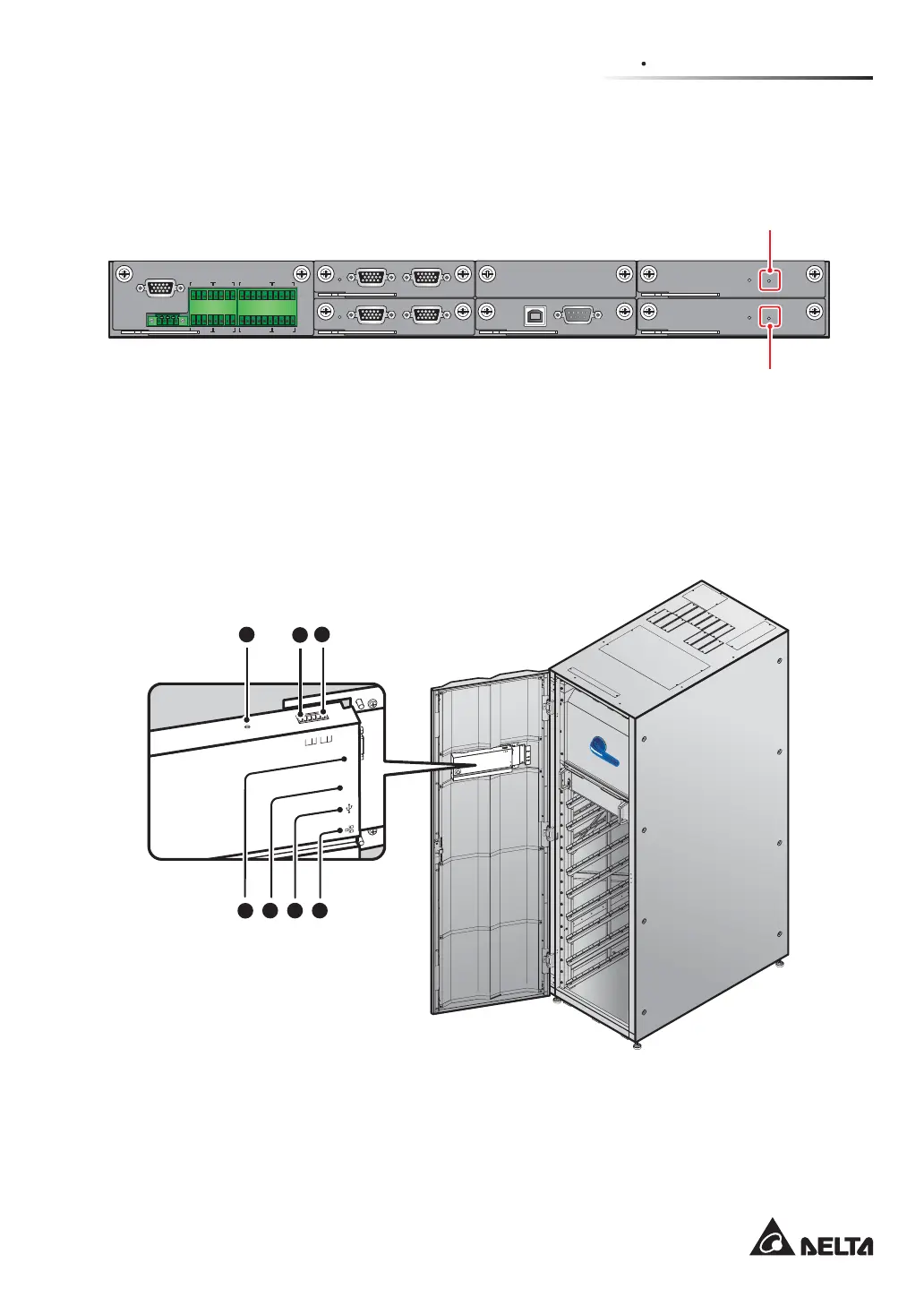
4.1.12
Battery Start Buttons
Please refer to 6.2.2 Battery Mode Start-up Procedures for relevant information.
DISPLAY
REPO
NC NO
EXT. BATT
TEMP.
BT1 BT2
EXT.SWITCH
STATUS
S1 S2
S3 S4
BT3
BT4
O/P DRY
CONTACT
USB RS-232
P1 P2 P3
P4
P5 P6
I/P DRY
CONTACT
P1 P2
BATT.
START
BATT.
START
P3
P4
PARALLEL
PAR ALL EL
Battery Start Button
Battery Start Button
(Figure 4-14: Location of Battery Start Buttons)
4.2 Communication Interfaces at the Rear of the Touch Panel
The following communication interfaces are located at the rear of the touch panel. Please see
the description below.
MO
DBUS
B
MS
RE
SET
G
N
D
B
A
G
N
D
B
A
DISPLAY
EMS
ICONSOLE
ON I
BYPASS SWITCH
(Front View with Door Open)
MODBUS
BMS
GND
B
A
GND
B
A
DISPLAY
EMS
ICONSOLE
RESET
5
6 7
1 2
3
4
(Figure 4-15: Communication Interfaces_ at the Rear of the Touch Panel)