4-12
Modulon DPH Series
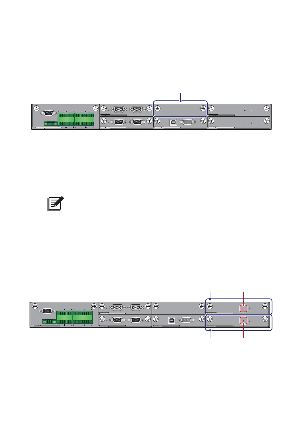
4.1.9 SMART Slot
You can install the optional Relay I/O card (for dry contact expansion) into the SMART slot
shown in Figure 4-12. For relevant installation and application information, please contact
Delta customer service.
DISPLAY
REPO
NC NO
EXT. BATT
TEMP.
BT1 BT2
EXT.SWITCH
STATUS
S1 S2
S3 S4
BT3
BT4
O/P DRY
CONTACT
USB RS-232
P1 P2 P3
P4
P5 P6
I/P DRY
CONTACT
P1 P2
BATT.
START
BATT.
START
P3
P4
PAR ALL EL
PARALLEL
SMART Slot
(Figure 4-12: SMART Slot Location)
4.1.10
USB Port & RS-232 Port
You can use the provided RS-232 cable or the USB cable to connect the UPS’s RS-232 port
or USB port with a computer, and use either the USB port or the RS-232 port to upgrade the
firmware of UPS, power modules, system control card and parallel communication cards and
download event logs.
127(Do not use the RS-232 port and the USB port at the same time.
4.1.11
Auxiliary Power Cards
The UPS has two auxiliary power cards. Each card has one LED indicator. Please see Figure
4-13 for their location.
If the auxiliary power card works normally, its LED indicator will illuminate green. If the
auxiliary power card is off or abnormal, its LED indicator will be off.
DISPLAY
REPO
NC NO
EXT. BATT
TEMP.
BT1 BT2
EXT.SWITCH
STATUS
S1 S2
S3 S4
BT3
BT4
O/P DRY
CONTACT
USB RS-232
P1 P2 P3
P4
P5 P6
I/P DRY
CONTACT
P1 P2
BATT.
START
BATT.
START
P3
P4
PARALLEL
PARALLEL
Auxiliary Power Card’s
LED Indicator
Auxiliary
Power Card
Auxiliary Power Card’s
LED Indicator
Auxiliary
Power Card
(Figure 4-13: Location of Auxiliary Power Cards and their LED Indicators)