6-35
6
ௐ
ௐ
UPS Operation
3
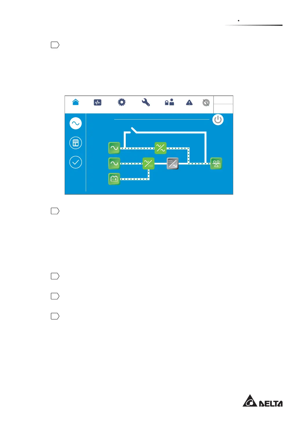
After selection of ‘YES’, the UPS will shut down the inverter, terminate each power
module’s output and let the bypass AC source supply power. If the bypass AC source
is abnormal, there is a risk of output interruption and the connected critical loads won’t
be protected. At this moment, each power module keeps charging the batteries, the tri-
color LED indicator illuminates yellow and the following screen appears (Figure 6-47).
For the tricolor LED indicator location, please refer to Figure 2-11.
Bypass
POWER FLOW
Maintenance
Bypass
Bypass
Mains
90 %
5 mins
Load
30 %
MEASUREMENT
Power Flow
UPS-1.1 SETUP MAINTENANCE EVENT LOG
Power Flow
Summary
System Status
LOG IN
User
10:15
May 25,2018
(Figure 6-47: Bypass Mode Screen)
4
Single Input:
Switch OFF the UPS’s bypass switch (Q0), Delta or non-Delta external maintenance
bypass cabinet’s input breaker or switch (Q1) and output breaker or switch (Q4).
Dual Input:
Switch OFF the UPS’s bypass switch (Q0), Delta or non-Delta external maintenance
bypass cabinet’s input breaker or switch (Q1), bypass breaker or switch (Q2) and output
breaker or switch (Q4).
5
Now, each power module performs DC BUS discharging and its LED indicator flashes
green. After discharging, each power module’s LED indicator will be off.
6
About 3 minutes later, the UPS will shut down. After that, the LCD and the tricolor LED
indicator will be off.
7
Switch OFF every external battery cabinet’s breaker (Q5).




 To Next Page