6-37
6
ௐ
ௐ
UPS Operation
3
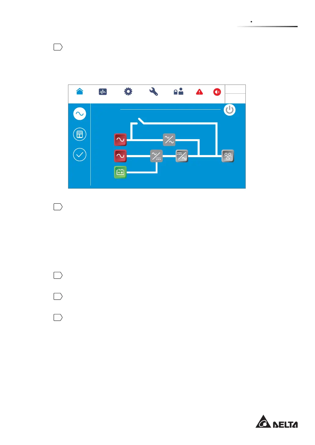
After selection of ‘YES’, the UPS will shut down the inverter, terminate each power
module’s output and transfer to run in standby mode. At this moment, the tri-color LED
indicator illuminates yellow and the following screen appears (Figure 6-50). For the tri-
color LED indicator location, please refer to Figure 2-11.
Standby
POWER FLOW
Maintenance
Bypass
Bypass
Mains
90 %
5 mins
Load
0 %
MEASUREMENT
Power Flow
UPS-1.1 SETUP
MAINTENANCE
Power Flow
Summary
System Status
LOG IN
User
2
WARNING
10:15
May 25,2018
(Figure 6-50: Standby Mode Screen)
4
Single Input:
Switch OFF the UPS’s bypass switch (Q0), Delta or non-Delta external maintenance
bypass cabinet’s input breaker or switch (Q1) and output breaker or switch (Q4).
Dual Input:
Switch OFF the UPS’s bypass switch (Q0), Delta or non-Delta external maintenance
bypass cabinet’s input breaker or switch (Q1), bypass breaker or switch (Q2) and output
breaker or switch (Q4).
5
Now, each power module performs DC BUS discharging and its LED indicator flashes
green. After discharging, each power module’s LED indicator will be off.
6
About 3 minutes later, the UPS will shut down. After that, the LCD and the tricolor LED
indicator will be off.
7
Switch OFF every external battery cabinet’s breaker (Q5).
 Loading...