3-3
3
ௐ
ௐ
Operation Modes
127(If there are switches but not breakers installed in the external
maintenance bypass cabinet, please install (1) an additional protective device
between the input power and the external maintenance bypass cabinet and (2)
an additional protective device between the connected critical loads and the
external maintenance bypass cabinet. The protective device could be a breaker
or a fuse. For the protective device’s rating current, please refer to the table
below.
200kVA 300kVA 400kVA 500kVA
400A 600A 800A 1000A
2. In this user manual, the meaning of Q0, Q1, Q2, Q3, Q4 and Q5 represents the following.
Code Meaning
Q0 UPS’s Bypass Switch
Q1
Delta or non-Delta External Maintenance Bypass Cabinet’s Input Breaker
or Switch
Q2
Delta or non-Delta External Maintenance Bypass Cabinet’s Bypass Breaker
or Switch
Q3
Delta or non-Delta External Maintenance Bypass Cabinet’s Manual Bypass
Breaker or Switch
Q4
Delta or non-Delta External Maintenance Bypass Cabinet’s Output Breaker
or Switch
Q5 External Battery Cabinet’s Breaker
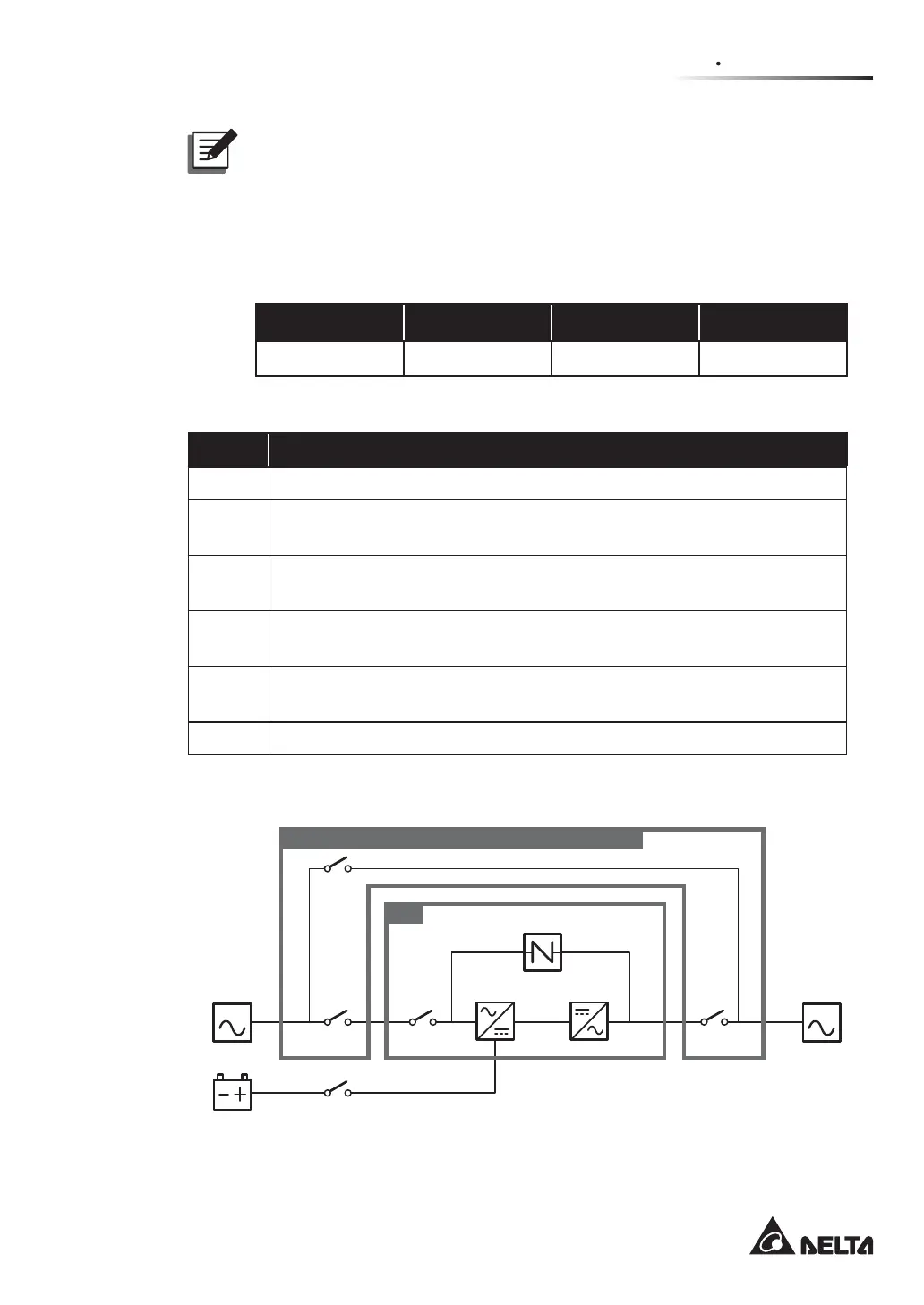
3. The structure of the UPS and the Delta or non-Delta external maintenance bypass cabinet
is shown in Figure 3-1 (single input application) and Figure 3-2 (dual input application).
MAIN LOAD
Q1 Q0 Q4
Q3
UPS
Q5
Batteries
Rectifier Inverter
Static Switch
Delta or non-Delta External Maintenance Bypass Cabinet
(Figure 3-1: Single Input Application_ UPS and Delta or non-Delta
External Maintenance Bypass Cabinet Structure)