5-11
5
ௐ
ௐ
Installation and Wiring
1
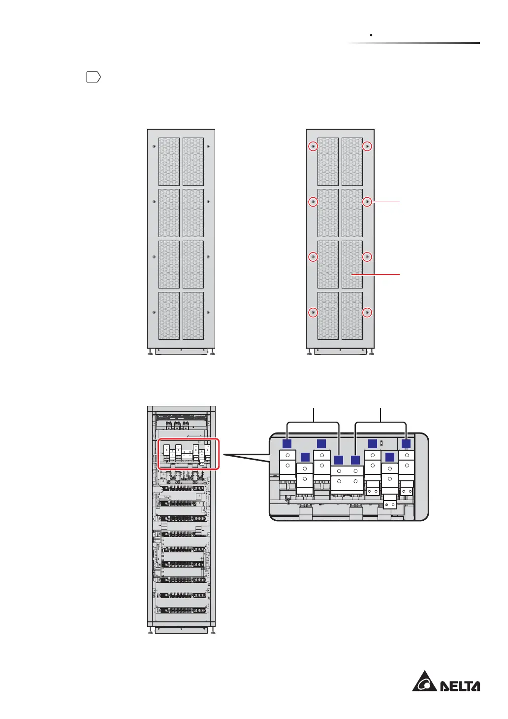
Unscrew the eight M5 screws to remove the rear panel (see Figure 5-5 and Figure
5-6). After removing the real panel, you will see the AC Input terminals and Bypass Input
terminals shown in Figure 5-7.
(Rear) (Rear)
Rear Panel
M5 Screw X 8
(Figure 5-5: UPS Rear View) (Figure 5-6: Rear Panel & Screw Location)
32
32
22 22 2221 21 21
32
32
32
32
35
BYPASS I/P
T
S
R
N
N
BYPASS I/P BYPASS I/P BYPASS I/P MAIN I/P
T
MAIN I/P
R
MAIN I/P
32
32
32
32
32
32
35
BYPASS I/P
T
S
R
N
N
BYPASS I/P
BYPASS I/P BYPASS I/P MAIN I/P
T
MAIN I/P
R
MAIN I/P
T T
S S
R R
N N
(Rear View after Rear Panel Removal)
Bypass Input Terminals AC Input Terminals
(Figure 5-7: Wiring Terminals_ AC Input & Bypass Input)
 Loading...