5-16
Modulon DPH Series
4
For how to perform wiring between the UPS and the Delta or non-Delta external
maintenance bypass cabinet, please refer to Table 5-3. For the detailed information
about the Delta or non-Delta external maintenance bypass cabinet, please refer to
5.1 Before Installation and Wiring.
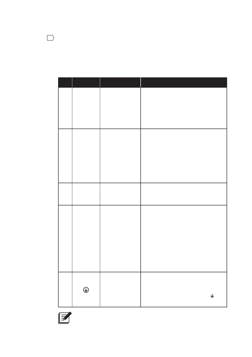
Table 5-3: Wiring between the UPS and the Delta or non-Delta External
Maintenance Bypass Cabinet
No. Item*
1
Description Function
1
AC Input
Terminals
Include R/ S/ T/
N terminals.
• Single Input: There is no need to
connect these AC Input Terminals.
• Dual Input: The terminals connect
to the Delta or non-Delta external
maintenance bypass cabinet’s input
breaker or switch (Q1).
2
Bypass
Input
Terminals
Include R/ S/ T/
N terminals.
• Single Input: The terminals connect
to the Delta or non-Delta external
maintenance bypass cabinet’s input
breaker or switch (Q1).
• Dual Input: The terminals connect
to the Delta or non-Delta external
maintenance bypass cabinet’s bypass
breaker or switch (Q2).
3
UPS
Output
Terminals
Include R/ S/ T/
N terminals.
Connect to the Delta or non-Delta
external maintenance bypass cabinet’s
output breaker or switch (Q4).
4
Battery
Input
Terminals
Include +/ -/ N
terminals.
• If you choose to use the Delta external
maintenance bypass cabinet (optional),
please connect these terminals to
the Delta external maintenance
bypass cabinet’s Battery Input
Terminals.
• If you choose to use the non-Delta
external maintenance bypass cabinet,
please contact service personnel for
battery configurations.
5
Includes one
grounding
terminal (for the
UPS’s protective
earthing).
• Connects to the Delta or non-Delta
external maintenance bypass
cabinet’s grounding terminal (
).
127(*
1
The items listed in the above ‘Item’ column are all located at the
rear of the UPS. Please refer to Figure 5-12 ~ Figure 5-14.