5-23
5
ௐ
ௐ
Installation and Wiring
UPS 1
UPS 2
UPS 8
3Ø4W
3Ø4W
Main AC Source
Loads
AC Input
Terminals
AC Input
Terminals
AC Input
Terminals
UPS Output
Terminals
Parallel Port
Parallel Port
Parallel Port
Parallel Port
Parallel Port
Parallel Port
UPS Output
Terminals
UPS Output
Terminals
Parallel Cable
Parallel Cable
Parallel Cable
Daisy
Chain
Method
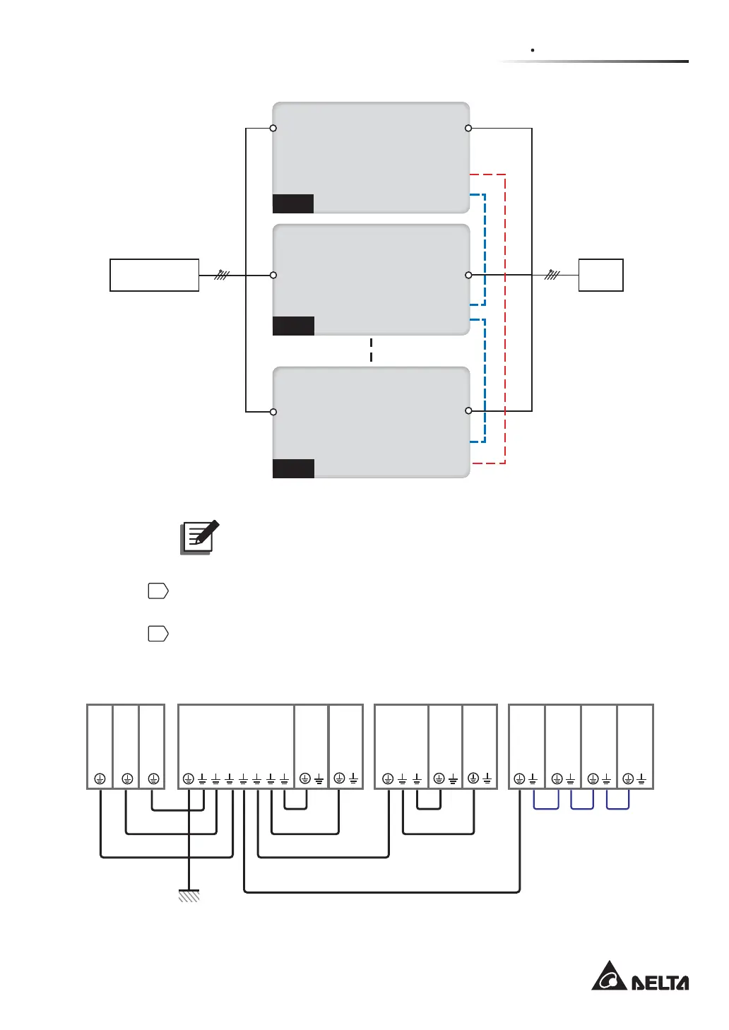
(Figure 5-18: Parallel Units Single Input Wiring Diagram)
127(The UPS will not work normally if the main AC source’s neutral (N)
is not firmly connected or not connected to the Delta or non-Delta External
Maintenance Bypass Cabinet’s AC Input neutral (N) terminal.
6
Use the provided parallel cable to connect the parallel ports on the parallel units,
Please refer to Figure 4-3 for the parallel port location.
7
Follow Figure 5-19 to ground the parallel UPS units, external battery cabinet(s),
Delta or non-Delta external maintenance bypass cabinets and the connected critical
loads.
(UPS: At Maximum 8 Units)
UPS UPS UPS UPS
UPS
Grounding
UPS Grounding
UPS
Grounding
UPS Grounding
External Battery Cabinet Grounding
Load Load Load
Delta or non-Delta External
Maintenance Bypass Cabinet Grounding
External
Battery
Cabinet
External
Battery
Cabinet
External
Battery
Cabinet
External
Battery
Cabinet
Protective Earthing
Load Grounding
Load
Grounding
Load Grounding
Delta or non-Delta
External Maintenance
Bypass Cabinet
Delta or
non-Delta
External
Maintenance
Bypass
Cabinet
(UPS: At Maximum 8 Units) (At Maximum Four)
(Figure 5-19: Grounding Diagram_ Parallel Units)
 Loading...