PBX Cascading Putting a Cascaded PBX into Operation
123
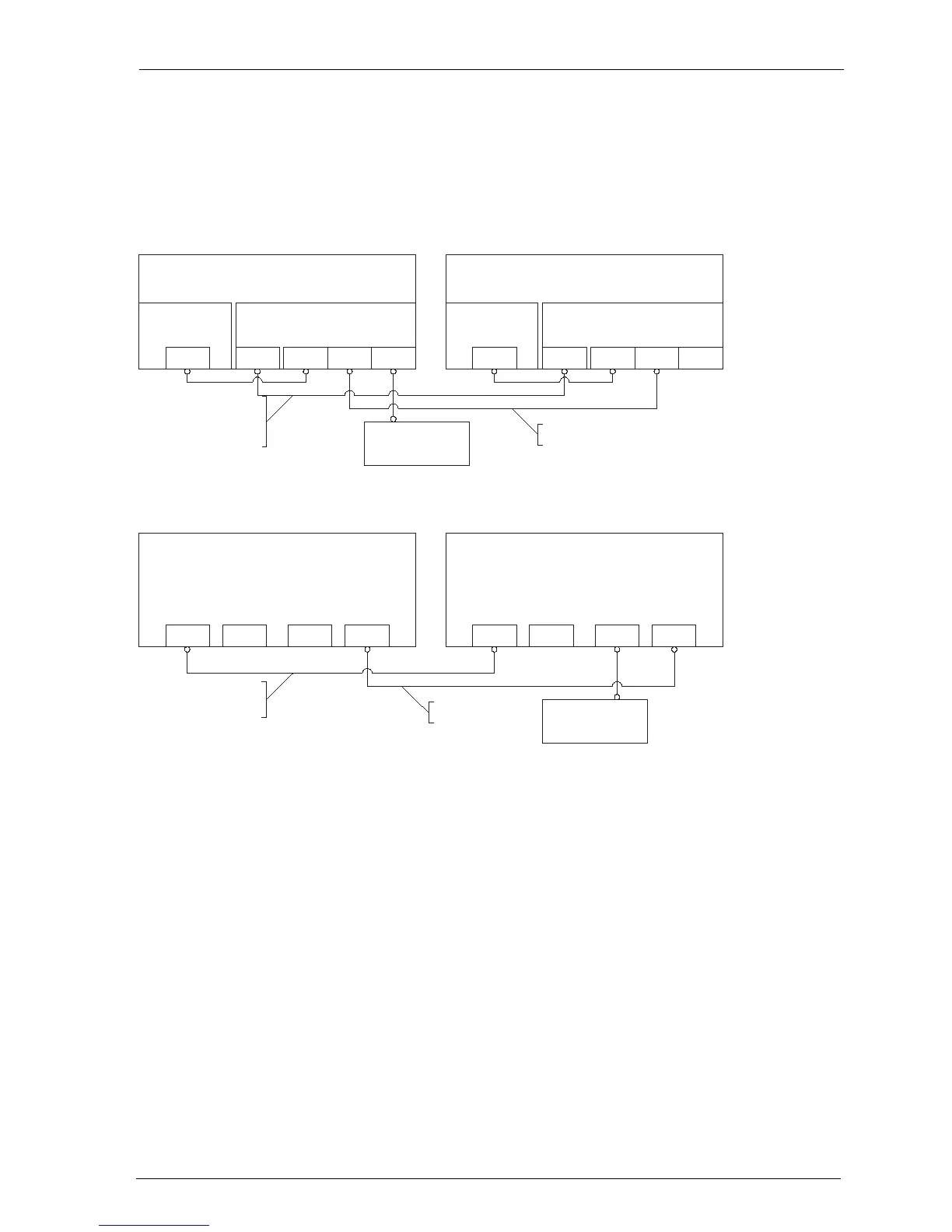
– In the case of an OpenCom 130, connect the LAN2 port of the master
system’s add-on module with a LAN2 port of the slave system’s add-on module.
– In the case of an OpenCom 150, connect the LAN1 port of the master system
with a LAN1 port of the slave system.
Cascaded PBX system (OpenCom 130)
Cascaded PBX system (OpenCom 150)
11.3 Putting a Cascaded PBX into Operation
Proceed as follows to put a cascaded PBX system into operation:
1. Take the additional slave system out of its packaging and place it in immediate
proximity to the master system. Connect a system telephone to the slave
system for a later performance check. Use the U
pn
1 press-fit terminal of the
basic module (only OpenCom 130) or one of the U
pn
ports of an interface card.
2. Back up the master system data. For further information, refer to the online
help topic SYS Configuration: Data Backup.
PBX 1
(Master)
Basic module Add-on module
PCM LAN1 LAN2 LAN0LAN
PBX 2
(Slave)
Basic module Add-on module
PCM LAN1 LAN2 LAN0LAN
Hub/Switch
(in LAN of company)
Voice data lead
(eight pins assigned,
joined 1 to 1)
CAT-5 Ethernet lead
PBX 1
(Master)
PCM2 LAN0 LAN1PCM1
PBX 2
(Slave)
PCM2 LAN0 LAN1PCM1
Hub/Switch
(in LAN of company)
Voice data lead (eight pins
assigned, joined 1 to 1)
CAT-5 Ethernet lead