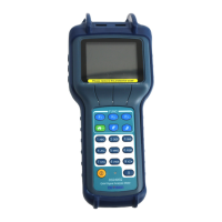
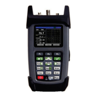
Handheld Cable/Antenna Analyzer
Chapter 7 — DTF Measurement Testing
Introduction
This chapter provides an overview of performing
Distance-to-Fault
(DTF)
measurements with E7000L
SitePROFILER. While reflection measurements express a cell site’s RF transmission efficiency, DTF
measurements actually identify the location of a specific fault (impedance mismatch) within the cable and
antenna system.
Since reflection measurements verify the impedance discontinuity of the total feedline system, it is crucial to
perform DTF measurements to identify the exact component degrading the line system’s performance.
Here, the instrument transmits a test signal along the conductor or transmission medium. If the conductor is
of uniform impedance and properly terminated, the entire transmitted signal will be absorbed in the far-
end termination and no signal will be reflected toward the instrument. Any impedance discontinuities will
cause some of the incident signal to be sent back towards the source.
Higher impedance creates a reflection that reinforces the original signal, while lower impedance creates a
reflection that opposes the original signal. The resulting reflected signal is plotted as a function of time. In
addition, because the speed of signal propagation is relatively constant for a given transmission medium, it
can also be read as a function of cable length. The SitePROFILER can verify cable impedance
characteristics, splice and connector locations and associated losses, and estimate cable lengths or faulty
location.
To begin a Distance-to-Fault measurement, press the
Menu
button to open the measurement mode
desktop, then tap the
Cable & Antenna
mode icon. Tap the Measurement main menu key along the
bottom of the display, then open the Standard submenu and choose a DTF measurement.
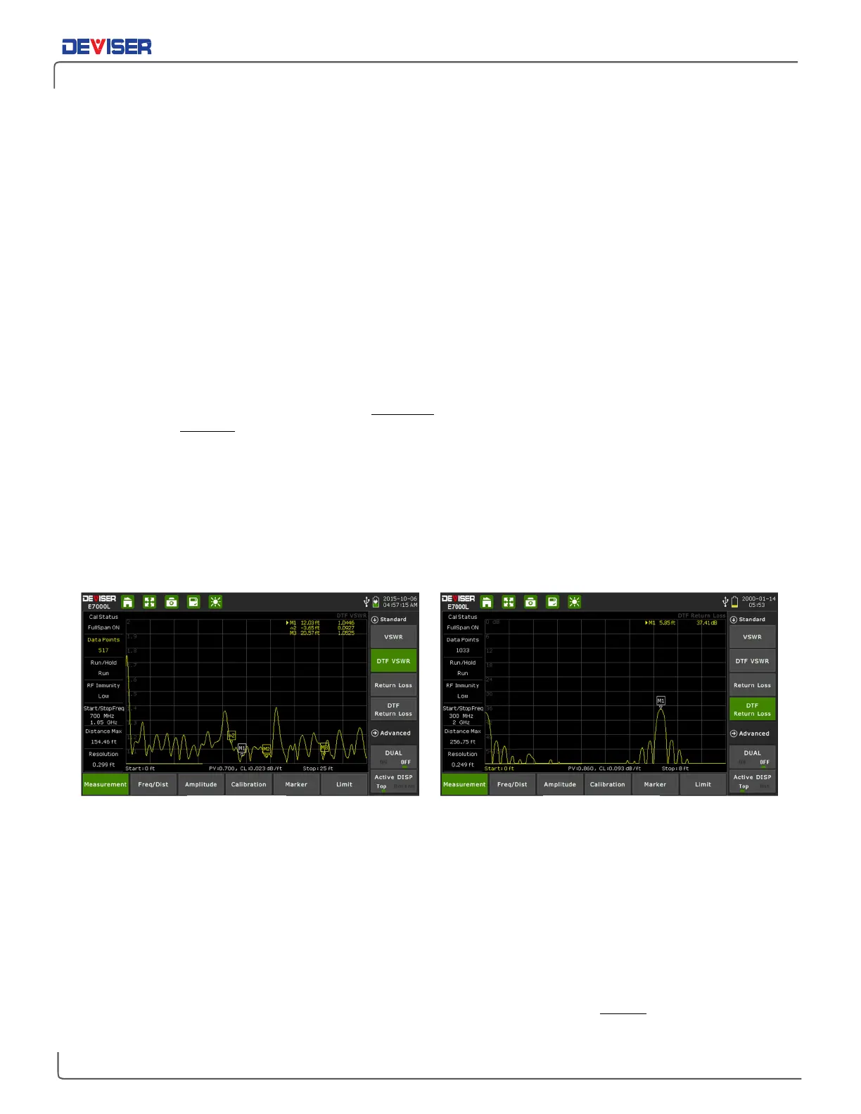
Which DTF measurement should I use?
Your specification (test procedure) will ordinarily direct you to make either a DTF Return Loss or DTF VSWR
measurement. Typically,
site sweeps
are performed in DTF Return Loss mode. This is because it is easier to
spot subtle differences and compare large and small values in the DTF Return Loss logarithmic display.
For your convenience, the E7000L SitePROFILER can perform DTF Return Loss and DTF VSWR sweeps
simultaneously while in
Dual Display
mode.
NOTE: The larger the values of the DTF Return Loss measurement, the better the impedance match.
Thus a Return Loss measurement of 42dB represents a much better impedance match than one of
25dB. Conversely, in DTF VSWR, better impedance matches are indicated by smaller values.
DTF Return Loss