Handheld Cable/Antenna Analyzer
Chapter 11 — Inline High Power Meter
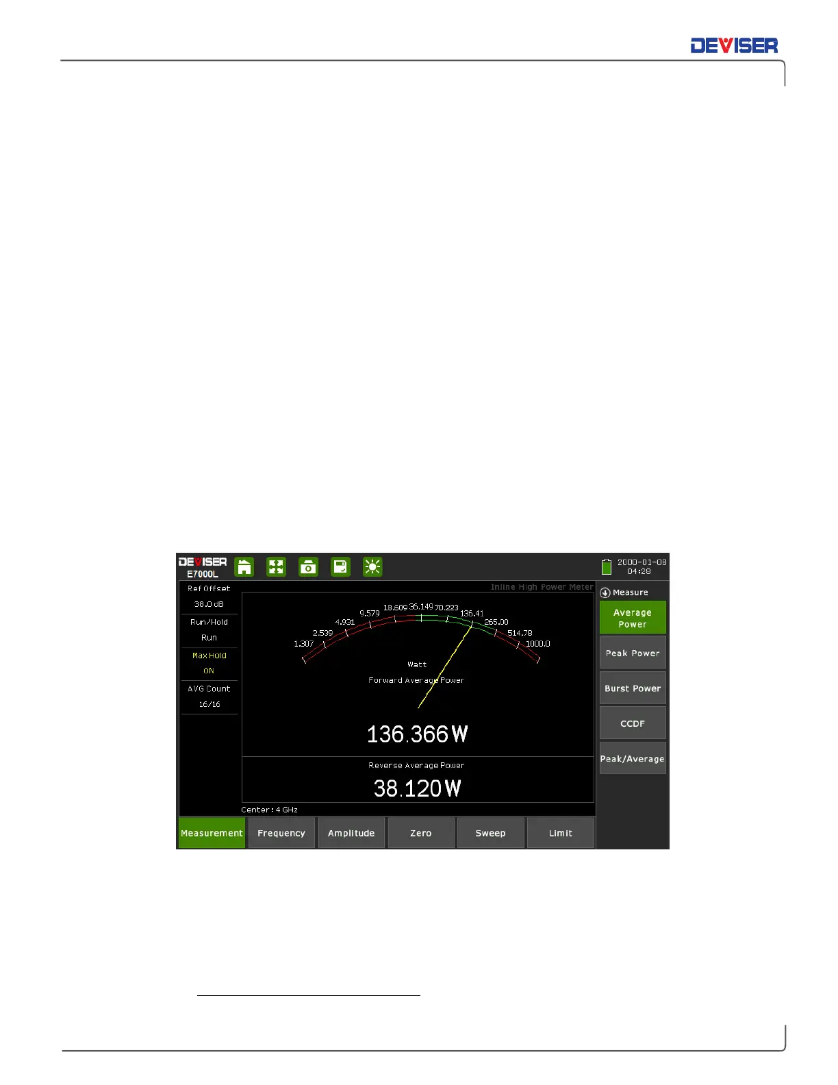
Introduction
The
Inline High Power Meter
measurement mode is intended to mimic a traditional thermal (thermo-
electric) power sensor. Therefore, it is ideal for measuring the average power of CW or modulated RF
waveforms such as 3G, 4G, OFDM, and multi-tone signals. In other words, it measures true RMS power
regardless of the type of input signal.
NOTE: Effective use of the Inline High Power Meter mode requires the external power sensor accessory
(PN: E7000-00500). All instructions in this chapter assume that the power sensor’s USB and RF In ports are
connected to the instrument via the USB and RF Out ports on the instrument’s top panel.
There are five different measurements within the Inline High Power Meter mode. Refer to the associated
section (in parentheses) for details on performing each measurement.
•
Average Power, Forward & Reverse (Section 11-1)
•
Peak Power (Section 11-2)
•
Burst Power & Duty Cycle (Section 11-3)
•
Complementary Cumulative Distribution Function (CCDF) (Section 11-4)
•
Peak-to-Average (Section 11-5)
Enter this measurement mode by pressing the
Menu
button to the top-right of the display, then selecting
the Inline High Power Meter icon.
Tips for Power Sensor Use:
Zero the sensor before making power measurements. If frequent low-level measurements are being made,
it is advised to check the sensor zeroing often and repeat as necessary. To zero the sensor, open the
Zero
main menu key and tap the
Zero
softkey. (This is not the same as the number “0” on the data keypad.)
The signal channel/analog signal acquisition hardware is integrated along with the RF front end of the
power sensor. All of the necessary frequency and temperature corrections take place within the sensor.
Therefore, there is no need for a reference calibration with the sensor.