Receives infrared signals from the remote con-
trol unit.
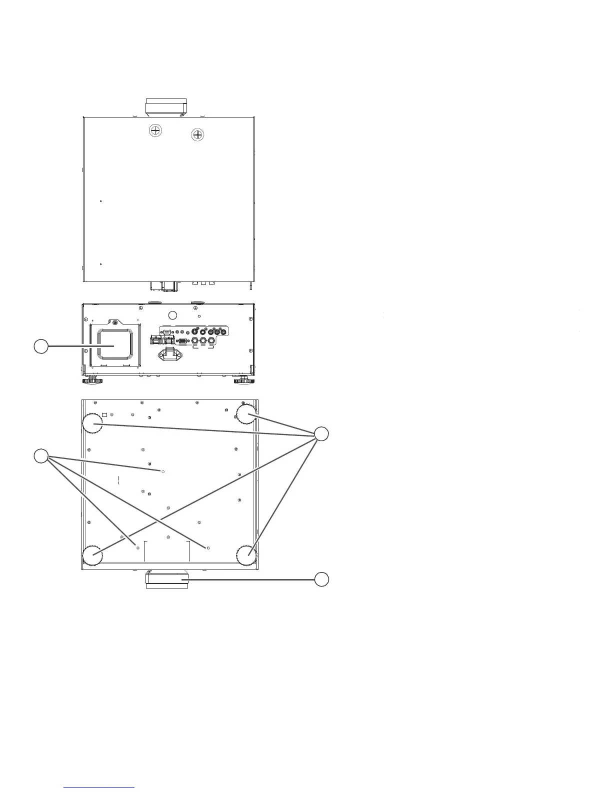
1. LAMP MODULE COVER
Remove this cover to access the lamp com-
partment.
2. ADJUSTABLE FEET
Use these when the projector is installed in a
table-top configuration to level the image and/
or adjust the projection angle.
3. BOLT MOUNTING PATTERN
Mounting holes are provided to secure the pro-
jector to a table or mounting plate to prevent
accidental movement. Below drawing is the
mechanical dimension for you to design a
mounting plate.
RS-232
1
H DMI
1
H DMI
2
12V
T
RIGGER
1 2
IR
INPUT S-VIDEO
V
I
DE
O
COMPONENT
1
-
SCAR
T
R
G
B
Y Pb
P
r
COMPONENT
2
AC
POWER
I
N
2
3
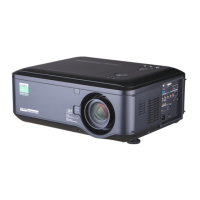
4. PROJECTION LENS
The inside of the lens barrel is threaded to ac-
commodate a standard, 72-mm lens filter. For
example, with a smaller screen you can install
4
a neutral-density filter to reduce the overall
light output.
Figure 2-2: Projector Rear/Bottom/Top View
11