Operating Instructions RF-2000
58
7.2 Control from External Equipment via RS-232C
An external device or data system such as CHROMELEON can control the RF-2000
using the RS-232C interface. This section explains how to connect the RF-2000 to an
external system and how to operate the RF-2000 using external control.
7.2.1 Connecting external equipment
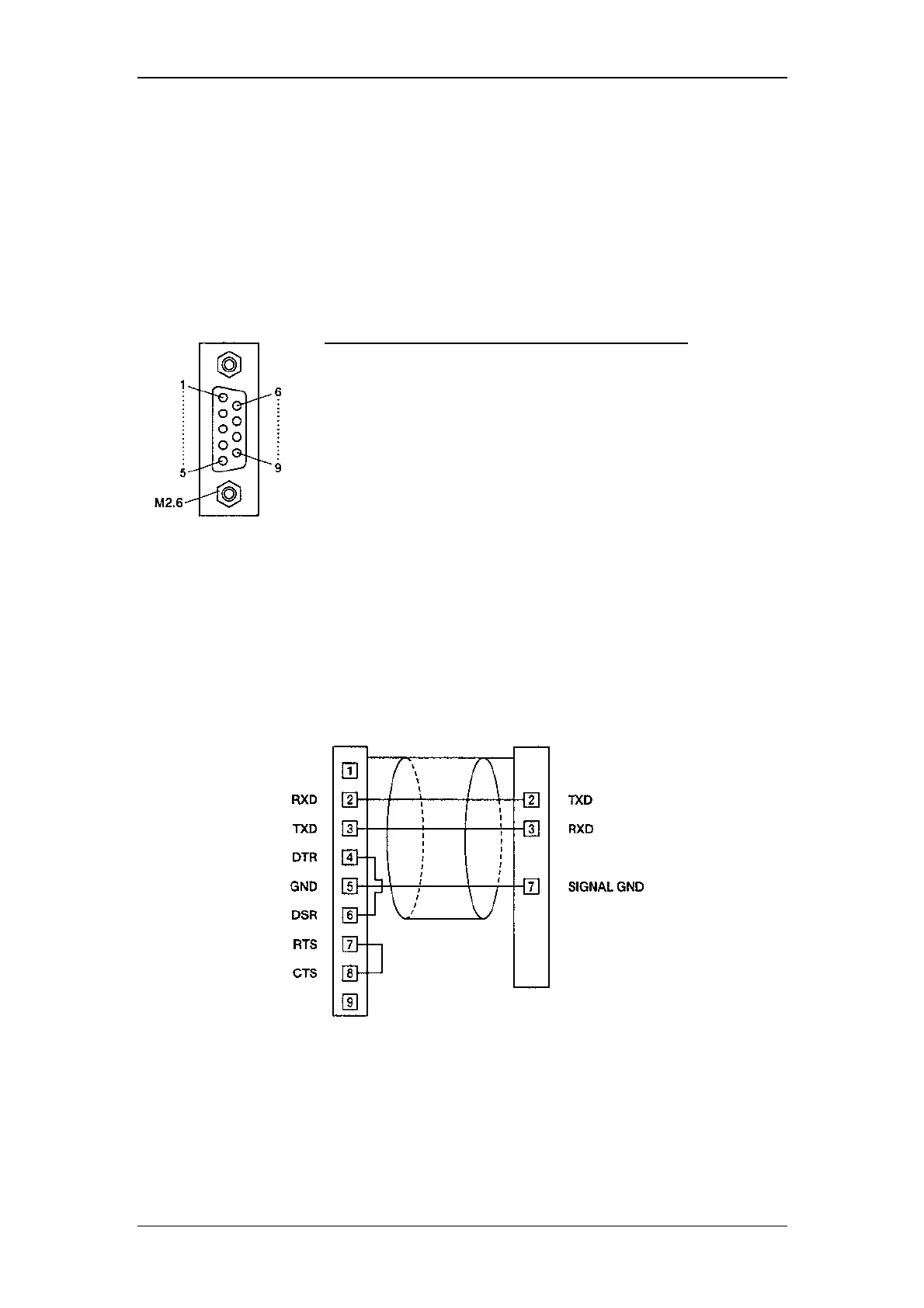
The pins of RS-232C terminal at the rear panel of the RF-2000 are defined as shown
in the figure below.
9-Pin Female
DSUB type connector
Use the optional RS-232C cable (part no. 8914.0115) for the connection between the
RF-2000 and a PC.
The figure below shows the connection in this cable.
PC side RF-2000 side
9-pin female DSUB Type
connector
9-pin male DSUB type connector
Pin No. Signal name Function
1 FG Frame grounding
2 T x D Output data line
3 R x D Input data line
4 NC Not connected
5 NC Not connected
6 NC Not connected
7 SG Signal grounding
8 NC Not connected
9 NC Not connected