revision: 1
FlexxPump 250/400 DLS
User Manual
21
EN-
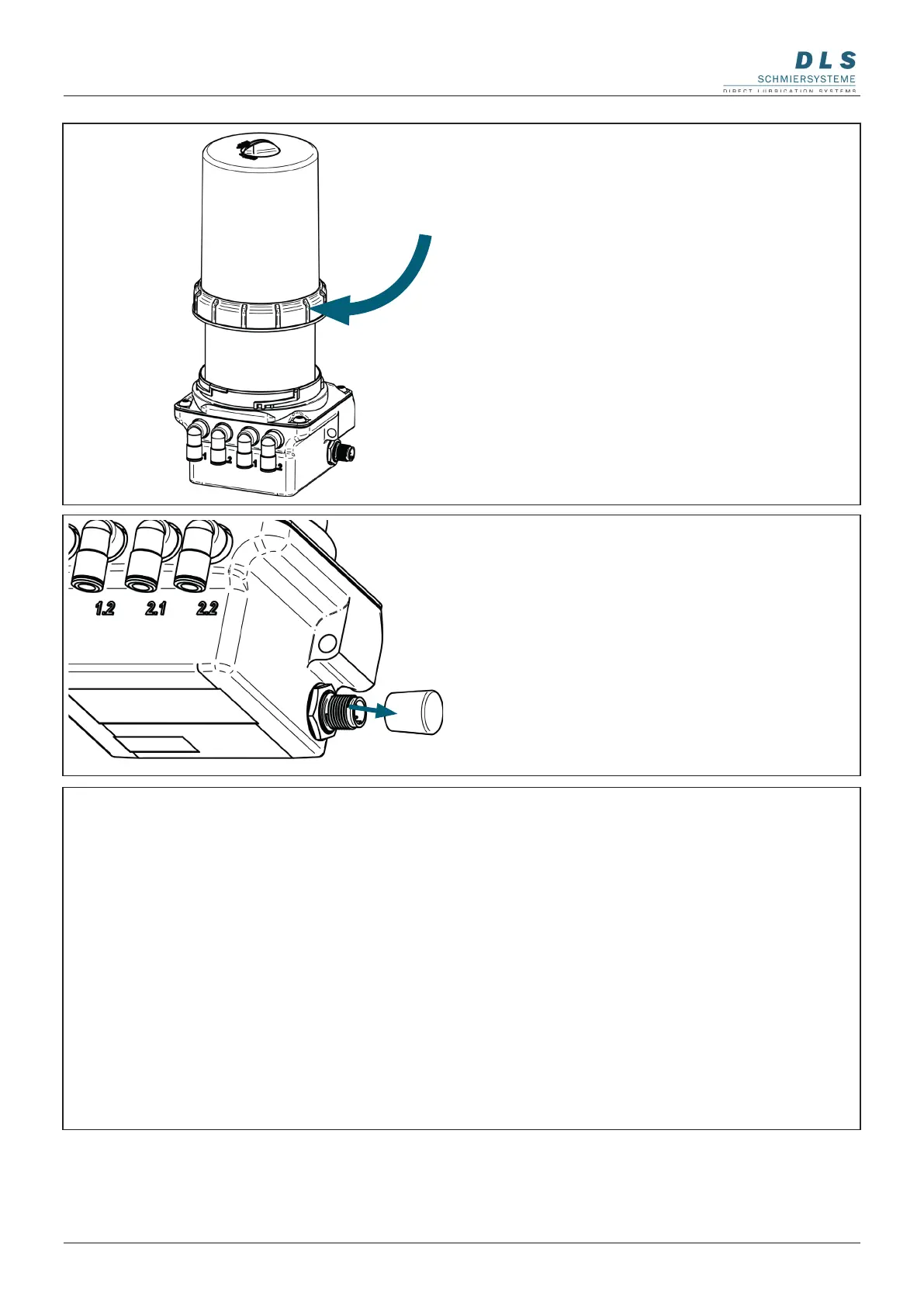
5. Remove the protective cap on the side of
the FlexxPump 250/400 DLS.
Remove the black protective cap from the
side of the electrical M12x1 interface.
6. Connect the electrical interface
Connect the FlexxPump 250/400 DLS
to the external power supply or controller
via the M12x1 interface on the side of the
FlexxPump 250/400 DLS using a suitable
connecting cable.
Depending on the application, both
connection cables with straight or angled
sockets can be used.
Please refer to chapter 8.1 for the condi-
tion of the connection cable.
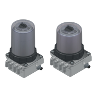
4. Assembling the housing on the power unit
of the FlexxPump 250/400 DLS.
Place the dismantled housing on the
FlexxPump 250/400 DLS and press it onto
the power unit.
Fasten the housing to the power unit by
turning the retaining ring clockwise.
The retaining ring must snap into place
when turning and be completely tightened.