SuperSigma2 QRM PMS – V01.02.02 17-1-2020 Page 54 (58) ©2019 DMC GmbH Herten Germany
11.4 CAN bus wiring
CAN bus communication wires should be terminated at both ends with a 120Ω resistor.
All SuperSigma2 controllers the 120Ω termination resistor installed, it is up to the user to use it or not.
By linking pin A24 and A25 on a SuperSigma2 controller the termination resistor becomes active.
If a CAN bus network is installed in a machine, special care should be taken which 2 CAN nodes should have the build-in
termination resistor connected. Make sure that only 2 termination resistors are active.
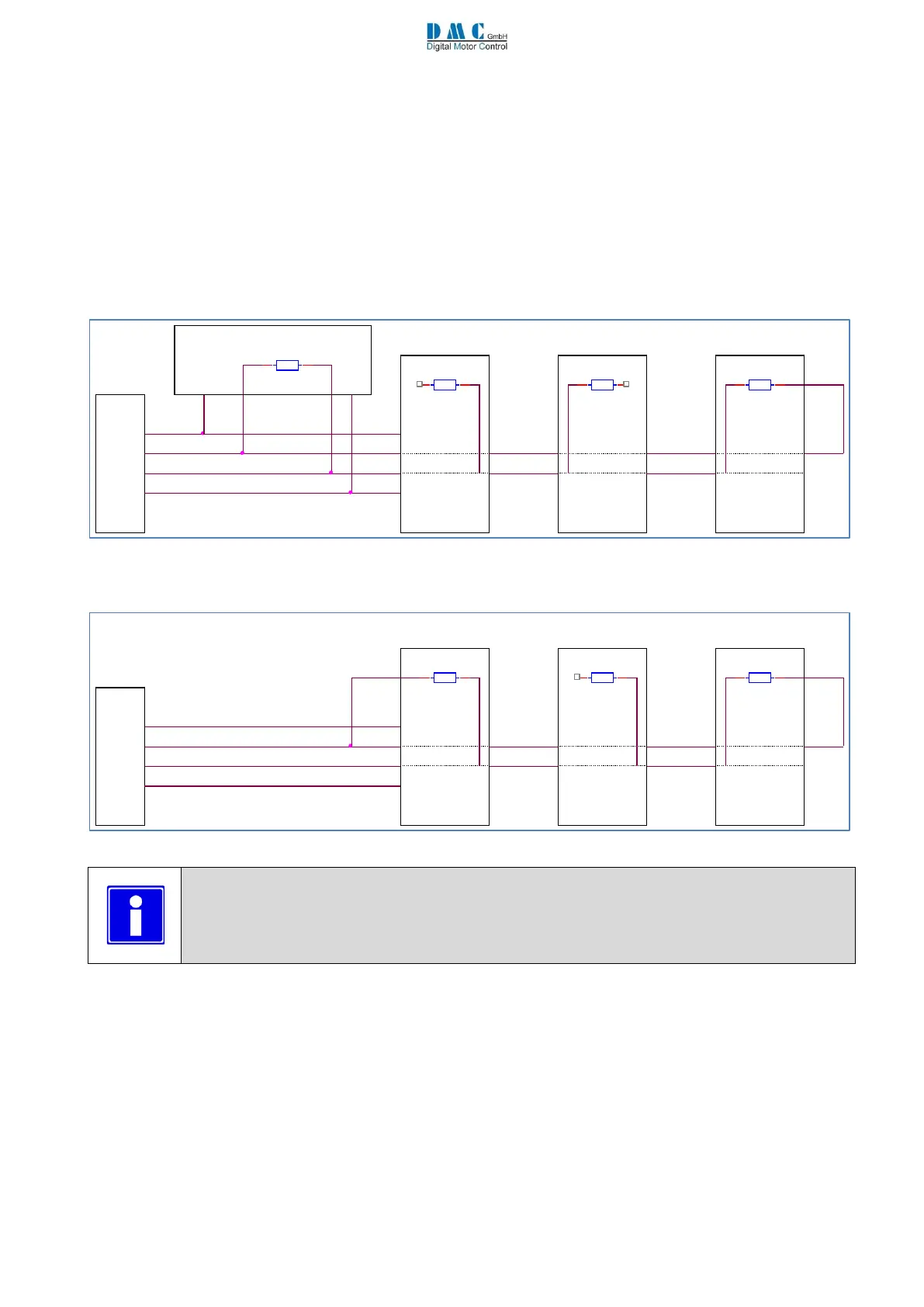
Below 2 examples of a CAN bus network, with and without DMC CAN Display.
11.4.1 CAN bus wiring example with DMC Display:
The DMC advanced display has a CAN bus termination resistor installed. This resistor is fixed installed and cannot be
disconnected. Below schematic shows how the CAN bus termination should be wired when a DMC advanced display is
part of the CAN bus installation:
11.4.2 CAN bus wiring example without DMC Display:
If no DMC advanced display is installed, wire as followed: