SuperSigma2 QRM PMS – V01.02.02 17-1-2020 Page 26 (58) ©2019 DMC GmbH Herten Germany
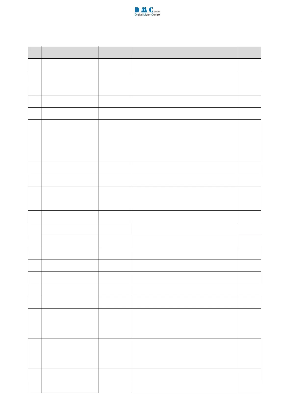
9.5.2 Controller Setup for Pump
A pump controller is always in speed control mode. Other changes to the Controller Setup compared to the traction
controller setup are:
Options (defaults are in bold)
0 = Accelerator linear
1 = Accelerator curved
Speed 6 input normally
closed or normally open
0 = Normally open
1 = Normally closed
Inhibit input normally
closed or normally open
0 = Normally open
1 = Normally close
0 = Don’t check
1 = Check
0 = No switch
1 = With switch
0 = None
1 = Accelerator [%]
2 = Motor Velocity [RPM]
3 = no effect
4 = no effect
5 = Motor current [A]
6 = Battery current [A]
0 = Remote LED
1 = Drive OK
Active low or high digital
inputs
0 = Active low digital inputs
1 = Active high digital inputs
Accelerator supply wire
off detection
0 = No supply wire off detection
1 = 0V wire off detection enabled
2 = 5V wire off detection enabled
3 = Both 0V and 5V wire off detection
Line Contactor pull-in
level
Adjustable from 50% to 100% Ubatt.to limit inrush
current. Default is 90%
Line Contactor pull-in
time out
Line Contactor pull in time out. Default is 10sec.
Line Contactor Coil pull-in
Voltage
Adjustable from 5% to 100% Ubatt Default is
100%
Line Contactor Coil
Holding voltage
Adjustable from 5% to 100% Ubatt Default is
100%
Digital output 2 pull-in
voltage
Adjustable from 7% to 100% Ubatt Default is
100%
Digital output 2 hold
voltage
Adjustable from 7% to 100% Ubatt Default is
100%
Digital output 3 pull-in
voltage
Adjustable from 7% to 100% Ubatt Default is
100%
Digital output 3 hold
voltage
Adjustable from 7% to 100% Ubatt Default is
100%
Drive output 2
Configuration
0 = no function
1 = motor temperature cooling enabled
2 = controller temperature cooling enabled
3 = both motor and controller temperature
cooling enabled
Drive output 3
Configuration
0 = no function
1 = motor temperature cooling enabled
2 = controller temperature cooling enabled
3 = both motor and controller temperature
cooling enabled
Drive Output Motor Temp
TH
Adjustable from 10 to 127 °C. Default is 70 °C
Drive Output Controller
Temp TH
Adjustable from 10 to 100 °C. Default is 45 °C