Dobot M1 Pro Hardware User Guide
Issue V1.3 (2023-02-02) User Guide Copyright © Yuejiang Technology Co., Ltd
18
The Encoder interface of the M1 Pro is shown in Figure 6.2,Table 6.2 lists the description of
Encoder interface.
Figure 6.2 Encoder interface
Table 6.2 Encoder Interface description
Base I/O interface
A robot controller contains I/O interfaces, for connecting to external equipment, such as PLC,
etc. These I/O interfaces provide 16 digital inputs, 16 digital outputs, as shown in Figure 6.3.
Figure 6.3 I/O interface
NOTE
Digital output is powered by internal 24V power supply.
The output current of every DO can’t exceed 500mA.
The total current can’t exceed 2A.
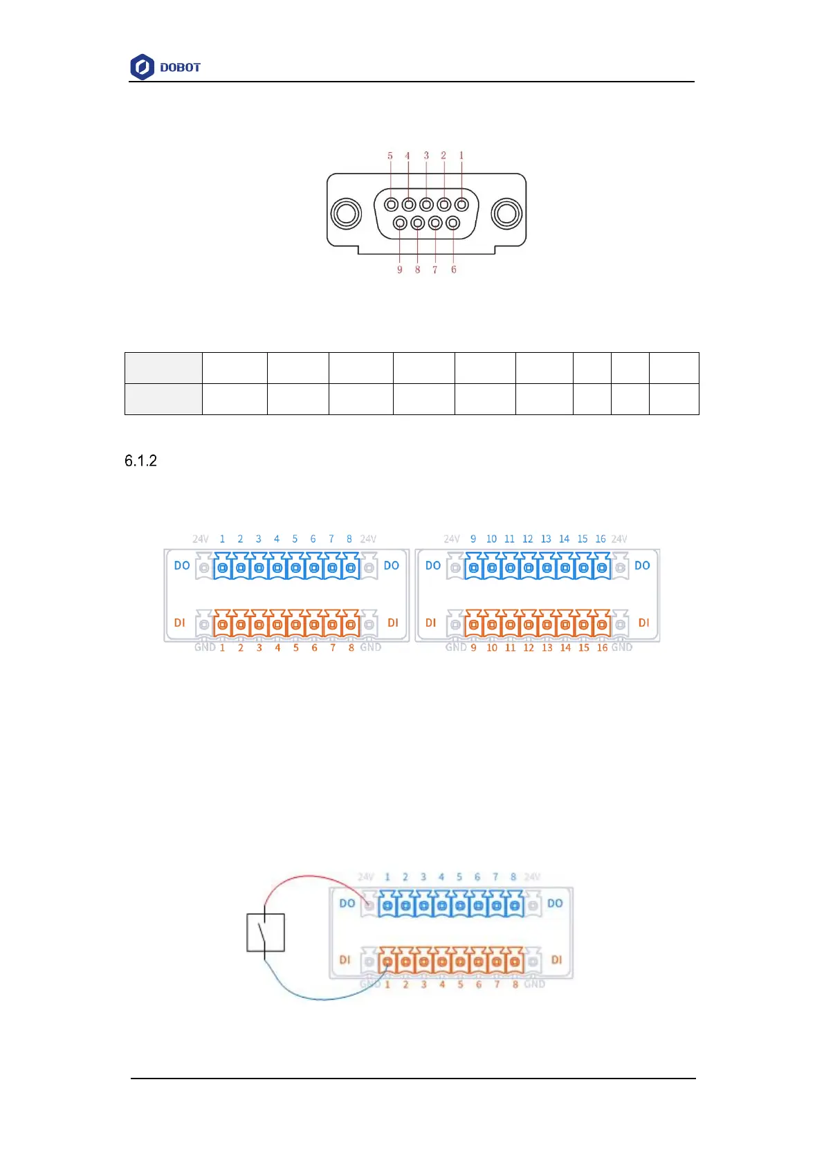
DI wiring
The wiring of DI connected to a simple switch is shown below.
Figure 6.4 DI connected to a simple switch