DOM Roq® Mounting and Connection of Pin Code Reader (Chip Reader) with DOM Roq®
59
DOM Roq® Smart Lock
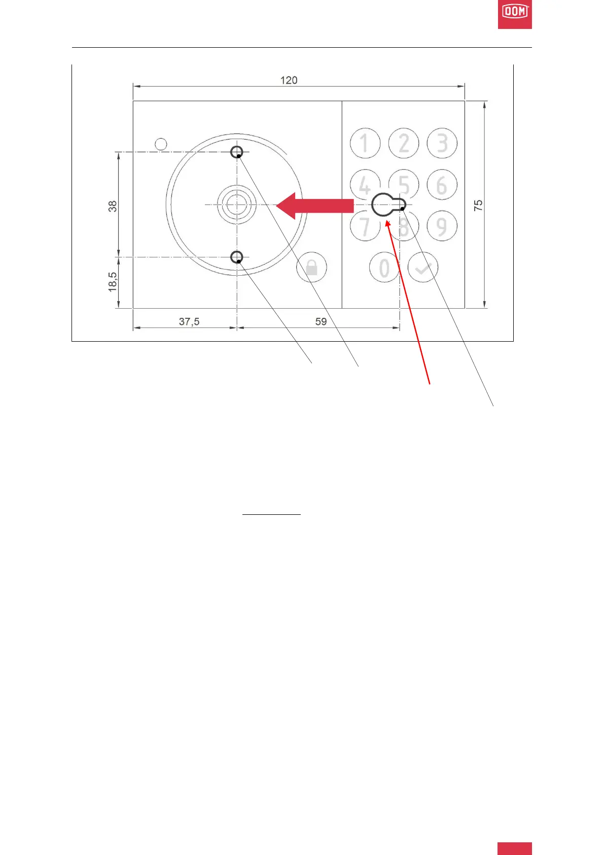
DOM Roq® Fig. 54: Mounting Instructions Pin Code Reader
Hole 3
Hole 2
Outlet Hole for Screw Head
Hole 1
(anchor hole)
2. Draw the hole pattern (as shown in Fig. 54) at the point where the chip reader should
be attached. (Points for hole 1-3)
3. Drill the appropriate holes (drill ø6 mm).
4. Insert the dowels into the pre-drilled holes.
5. Screw a screw into hole 1 (anchor hole), up to a distance of approx. 3 mm space be-
tween screw head and wall.
6. Place the base plate of the chip reader with the outlet hole over the screw head and
push it to the left over hole 1.
7. Check that the screw is turned in deep enough and that the base plate can just be
pushed on and is firmly seated in the anchor hole.
8. If this is not the case, slide the base plate to the right and remove it. Turn the screw in
a little further.
9. Repeat points 6 to 8 until the base plate has no more play after being pushed on.
10. Now fasten the base plate additionally with the two screws in hole 2 and hole 3.