1835-065-D-5-17
59
1. Press and enter your four-digit MASTER CODE (beep).
2. Press (beep).
PASS - The LCD display will indicate: RS232 HARDWARE PASS. One long tone will be heard: (Beeeeeep).
FAIL - The LCD display will indicate RS232 HARDWARE FAIL. Two short tones and a long tone will be heard:
(Beep - Beep - Beeeeeep).
3. Remove the jumper wires from the terminal after performing this test.
?
?
?
?
7
PQRS
1
SP
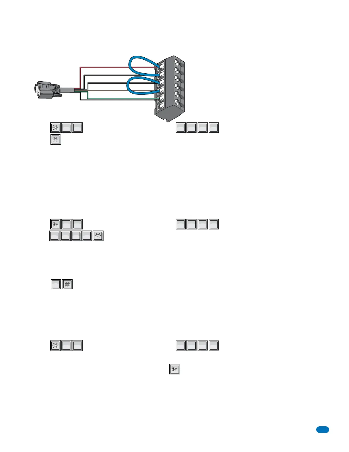
6.1.1 RS-232 Test
This test procedure will check the RS-232 hardware to determine a PASS or FAIL mode. You will need two short pieces of wire
to perform this test (jumpers). Connect the jumper wires as shown to the RS-232 terminal.
1
2
3
4
5
6
RS-232 Terminal
Red
Black
White
Brown
Green
Shield
The 6-pin terminal
can be removed
for easy wiring.
RS-232
DB-9 Pin
Plug
This programming sequence will allow you to view the wiegand data on the LCD display as it is received by the control board.
This will allow you to verify that the 26, 30 and 31-bit wiegand device is functioning properly.
1. Press and enter your four-digit MASTER CODE (beep).
2. Enter .
3. Activate one of the wiegand input devices by placing a card on a card reader, pressing a transmitter button, or entering a
digital code on a wiegand keypad.
4. If the wiegand data is shown on the LCD display, this verifies that the wiegand device is operating properly and sending the
information to the entry system. If NO data appears on the display, the wiegand devices are NOT functioning.
5. Press to cancel the wiegand test mode. (beeeeeep).
?
?
?
?
2
ABC
8
TUV
0
OPER
6.1.2 Wiegand Test - 1835 and 1837 Systems Only
9
WXYZ
9
WXYZ
9
WXYZ
9
WXYZ
This programming sequence is designed for troubleshooting the elevator control board(s) that may be connected to the
telephone entry system. This sequence will take approximately four (4) minutes to complete and will check the operation of the
CALL relay, all the odd numbered relays, then all the even numbered relays on the elevator control board(s). This test confirms
communication between the telephone entry system circuit board and the elevator control board(s).
6.1.3 Elevator Board(s) Hardware Test - 1835 and 1837 Systems Only
1. Press and enter your four-digit MASTER CODE (beep).
2. The LCD display will show: WHICH ELEVATOR?
3. Enter the elevator shaft number (1, 2, 3 or 4) _, then press (beep).
The LCD display will show: ELEVATOR TEST 1.
Once the test starts, the CALL relay (LED ON) will activate, then ALL odd numbered relays will activate. After that, ALL even
numbered relays will activate on the 1st elevator control board. After this sequence, if more than one elevator control board
is connected, ALL odd numbered relays, and then ALL even numbered relays will activate on the 2nd elevator control board.
This sequence will repeat itself up to ten (10) times depending on the number of elevator control boards connected.
4. Once the test is complete (approximately 4 minutes), this programming sequence will automatically end itself.
?
?
?
?
6
MNO
7
PQRS
 Loading...