REAR LOADER
6.4
2. With the engine and pump “on” place the upper
panel to the fully out position.
3. Move the lower panel control lever to shift the
spool in either direction. The lower panel will travel
to the end of the stroke but will not release the
dent and shift to the neutral position.
4. Slowly turn the main relief valve adjusting screw in
(clockwise) to increase the pressure. Watch the
pressure gauge to see what the pressure is when
the spool kicks out of dent and returns to the
neutral position. The correct kick-out pressure for
the lower panel is 2350 +/-50 PSI.
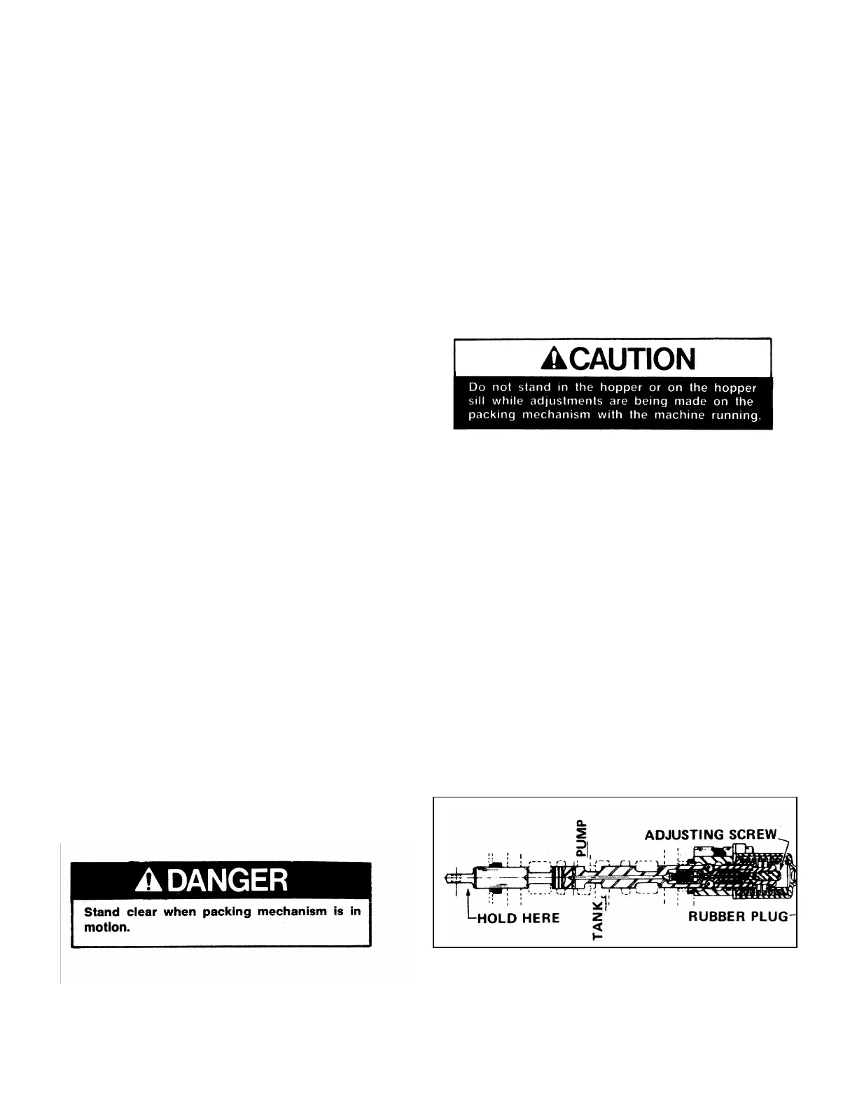
5. If the setting is incorrect, place the unit in the
lockout position and remove the rubber plug from
the end of the upper panel spool to expose the
dent release adjusting screw.
6. Insert a screwdriver and turn the dent adjusting
screw in (clockwise) to increase the kick-out
pressure or out (counterclockwise) to decrease the
pressure.
NOTE: Be careful not to force the adjusting screw or it
may deform the internal adjusting rod and make the
valve inoperative.
7. Repeat steps 1 through 4 to check the results.
Note: The upper panel has a hydraulic detent for
extend set @ 2400 PSI and mechanical detent for
retract function. and is adjusted mechanically. (see
Upper Panel Kick-out Adjustment Procedures).
A. TAILGATE VALVE
The packing mechanism is controlled by two levers at
the right rear corner of the tailgate. These levers
control the upper panel and the lower panel. Refer to
the operator’s manual for correct operation of these
two levers.
The upper and lower panel functions can be operated
independently by engaging one lever at a time.
TAILGATE CONTROL VALVE PRESSURE
SETTINGS
The tailgate valve has some pressure settings that are
adjustable. All valve pressure adjustments should be
made with the engine running at the normal operating
speed for the function that is being adjusted. Not all-
miniscule steps are listed below only the main action
steps are called out to simplify the procedure.
Common sense must be used during the minor steps
such as shutting off the pump to connect and
disconnect a hydraulic pressure gauge, unlocking and
locking an adjusting screw with a jam nut, reading the
pressure gauge, bottoming out (deadheading) a
function, etc. Generally hydraulic pressures are
normally increased by turning the pressure adjusting
screw clockwise or decreased by turning the pressure
adjusting screw counterclockwise. Follow the steps
below to adjust the pressures.
NOTE: ALWAYS SET UNIT IN LOCK-OUT/TAG OUT
BEFORE STARTING ANY PROCEDURE. SEE
FRONT OF SECTION FOR PROCEDURES.
A. Connect an accurate 0-3000 PSI liquid filled
pressure gauge to the gauge port quick disconnect
fitting used to check the main system pressure.
Adjust the lower panel hydraulic detent
Note: All mechanical linkage must be free of any
binding.
1. Lower the main relief pressure by turning the main
relief adjusting screw out (counter clockwise) 4 turns.
HYDRAULIC DETENT
ISSUED JUNE 2003 Printed in U.S.A.
©COPYRIGHT 2003, H.E.I.L.