11
Electrical connections
Electrical connections
— The electrical wiring may be laid and connected only by a qualified electrician,
who must also comply with the appropriate regulations – a screened or un-
screened cable (such as LiY, LiYCY) may be used.
2-wire connection
— Connection to central device with at least 2-wire cable, 0.5 (AWG 20) to 2.5 mm
2
(AWG 13).
Installing the 4 to 20 mA current loop on the transmitter
— For currents of 3 to 22 mA, a DC voltage between 16.5 V DC (3 mA),
or 8.0 V DC (22 mA) and 30 V DC must be present at the transmitter.
● Fit 2-wire connecting cable in cable gland, cut to length and strip ends
(approx. 80 mm / 3.15").
● Shorten the shield (if installed) to prevent short-circuiting:
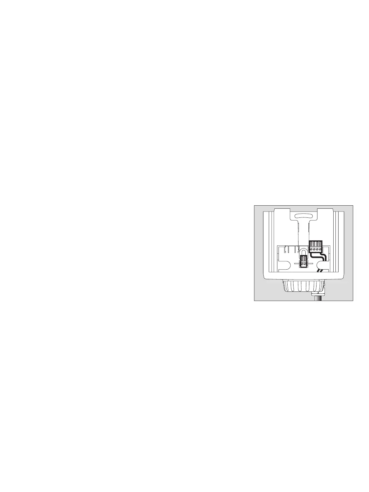
● Connect cable
1 Use a 4-pole terminal block (X8), Part No. 83 16 268, for the
Dräger Polytron 7000 – Observe the polarity of the connections.
Cut excess wires short or
2 secure them in centre terminals (Part No. 83 16 422).
1 Slide connecting terminal back into holder.
● Secure cable in holder.
● Fold up the installation notes and place them in the Dräger docking station for fu-
ture use during commissioning.
● Refit raincover (protection against dust and splashing water).
Connecting to the central unit
● Connect shield to earth of central unit (e.g. housing, earth bar, etc.).
Connecting the Dräger Polytron 7000 transmitter to a Dräger control unit
(such as Regard, QuadGard, Unigard or Polytron):
— Further information about the connection can be found in the instructions for
the Dräger control unit.
Connecting the Dräger Polytron 7000 transmitter to control units with
a 4 to 20 mA interfaced made by other manufacturers:
— For operation together with control units made by other manufacturers, care must
be taken that the voltage at the transmitter does not drop below 16.5 V at a current
of 3 mA and 8.0 V at a current of 22 mA. The supply voltage, the resistance of the
cable and the load and the resistance of any installed safety barrier must be taken
into account.
— Further information about the connection can be found in the instructions for the
control unit being used.
00723758_1.eps
1
X8
2
+24 V
0 V
0 V
Signal