17
Electrical connections
Connections between several transmitters and a control unit
with HART multidrop connections
● Each transmitter must first be put into service separately. Use the menu item "Poll-
ing Address" to assign a different polling address in the range "1" to "15" to each
transmitter which is to be connected to the multidrop cable (see page 69). It is
best to assign sequential polling addresses, starting with "1".
Installing the transmitters in areas subject to explosion hazards of zone 0 or
zone 1
● Depending on the supply unit, up to 7 transmitters can be connected to a 2-wire
or 3-wire cable.
The second cable gland is used for the cable to the next transmitter.
● Install a safety barrier with the appropriate explosion protection approval (catego-
ry 1, 2 or Div. 1) between the transmitter and the control unit.
— Only safety barriers with the following characteristics may be used: U
o
(V
oc
) ≤30
V, I
o
(I
sc
) ≤0.3 A, P
o
≤700 mW.
— Take care that the maximum permissible capacitance and inductance of connec-
tions to the safety barrier are not exceeded, also taking the cable into account.
The safety-related input parameters of the transmitter are: C
i
= 5 nF, L
i
= 50 μH.
— The safety barrier must be capable of transmitting the communications signals in
both directions between the explosion-hazard area and the non-explosion-hazard
area. Several manufacturers offer special SMART transmitter supply units for this
purpose.
SMART transmitter supply units
(with HART-communication between Ex/Non-Ex area)
The following safety barriers are provided as examples only and have not been certi-
fied for use in combination with the P3U. Selected barriers must be acceptable to
the authority having jurisdiction and comply with the assigned P3U entity parameters
also taking the cable into account.
— If a HART hand-held terminal is used, the permissible values may be lower. Ob-
serve the safety-related parameters of the hand-held terminal.
— The cable resistances given apply for the maximum possible number of transmit-
ters as well as a load resistance of 250 . Higher load resistances can drastically
reduce the maximum possible cable resistance!
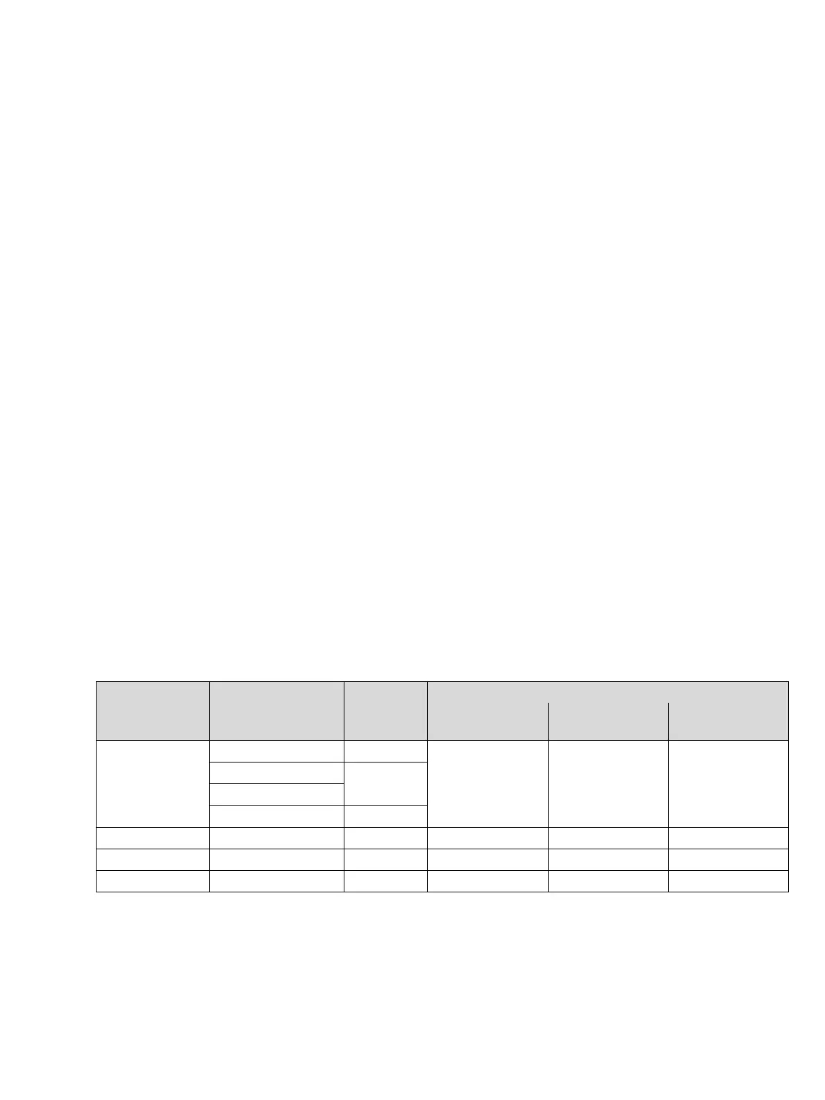
Manufacturer Type suitable for
R
Cable
(Total)
for up to
5 transmitters
for up to
6 transmitters
for up to
7 transmitters
Endress + Hauser
RN 221 N–B1 (ATEX) Zone 0
120 50 – – –
RN 221 N–C1 (FM)
Div. 1
RN 221 N–D1 (CSA)
RN 221 N–E1 (TIIS)
MTL MTL 5042 Zone 0, Div. 1 33 27 20
Pepperl & Fuchs KFD2–STC4–Ex1 Zone 0, Div. 1 90 10 – – –
Stahl 9160/13–11–11 Zone 0 160 80 20