Electrical connections
22
4-wire connection
— Connection to central device with at least 4-wire cable, 0.5 (AWG 20) to 2.5 mm
2
(AWG 13).
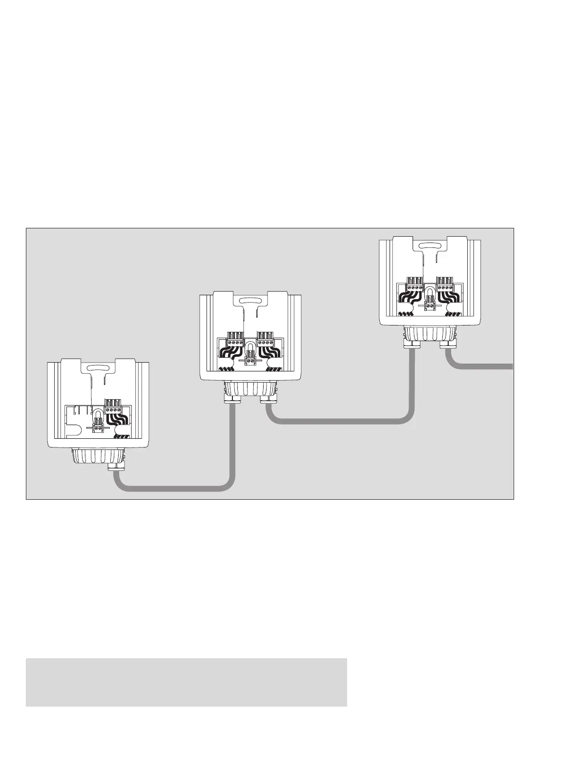
Installing the LON Communication on the transmitter
— For installation using LON communication up to 63 Polytron 7000 can be con-
nected to a four wire cable in any configuration including bus, star, loop and
mixed.
● Insert the 4-wire connecting cable in the cable gland, cut it to length and strip the
insulation (approx. 80 mm).
● Shorten the shield (if installed) to prevent short-circuiting:
● Connect cable
1 4-pin terminal for Dräger Polytron 7000 – observe polarity.
Slide connecting terminal back into holder.
● Secure cable in holder.
● Fold up the installation notes and place them in the Dräger docking station for fu-
ture use during commissioning.
● Refit raincover (protection against dust and splashing water).
Installing the transmitter in non-explosion-hazard areas:
Caution:
With 4-core connection the transmitter has no Ex protection. Once the trans-
mitter has been used after installation in this manner, it may never be installed
in explosion-hazard areas. Explosion hazard!
05723758_1.eps
0 V
Signal
Signal
24 V
0 V
Signal
Signal
24 V
0 V
Signal
Signal
24 V
0 V
Signal
Signal
24 V
0 V
Signal
Signal
24 V
X7 X8
X8X7
X8