29
Installing accessories
2 Loosen the bayonet ring of the remote sensor.
3 Place the retaining clip on the pipe of the case and install the bayonet ring again.
● Insert the sensor opening into the sealing sleeve.
● Turn the retaining clip to the correct position and screw it down.
Removal/changing the sensor
● Loosen the securing screws.
● Swing the retaining clip to one side.
● Pull the remote sensor out of the sealing sleeve.
● Change the sensor.
● Install the remote sensor again.
Dräger Polytron 7000 software dongles
Intended use
Dräger Polytron 7000 software dongle – 83 17 618, 83 17 619 or 83 17 860:
— For activating additional functions in the Dräger Polytron 7000:
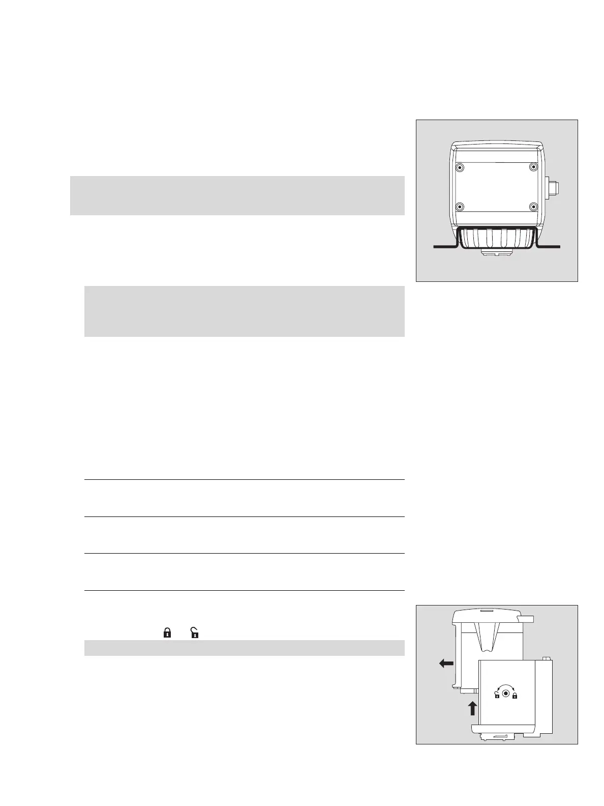
Installing the software dongles
1 Release the measuring unit with an Allen key by turning the eccentric catches
counter-clockwise (
⇒ = approx. 180
o
).
2 Push the measuring unit up to about half height and then pull it forwards out of
the docking station.
— The unit must be disconnected from the mains!
Note:
To avoid faulty measurements, pay close attention to the fitting of the sensor
in the sealing sleeve!
Attention:
For use in Zone 22, tighten the locking screw (2 mm Allen screw) of the
sensor bayonet ring tight enough to ensure that the bayonet ring is
secured against unintended loosening.
Data Dongle
83 17 618
Colour-code blue
— Activates the Event Logger, the Datalogger
and the graphical concentration display.
Sensor Dongle
83 17 619
Colour-code silver
— Activates the sensor self-test.
Sensor Diagnostic Dongle
83 17 860
Colour-code green
— Activates the sensor self-test, the display of
the remaining sensor lifetime and the sensor di-
agnostic function.
Caution! Use only a 5 mm Allen key without a ball head.
02423758_1.eps
2
3
02523758_1.eps
2
1