Electrical connections
16
Connecting the Dräger Polytron 7000 transmitter to control units with
a 4 to 20 mA interfaced made by other manufacturers:
— Further information about the connection can be found in the instructions for the
control unit being used.
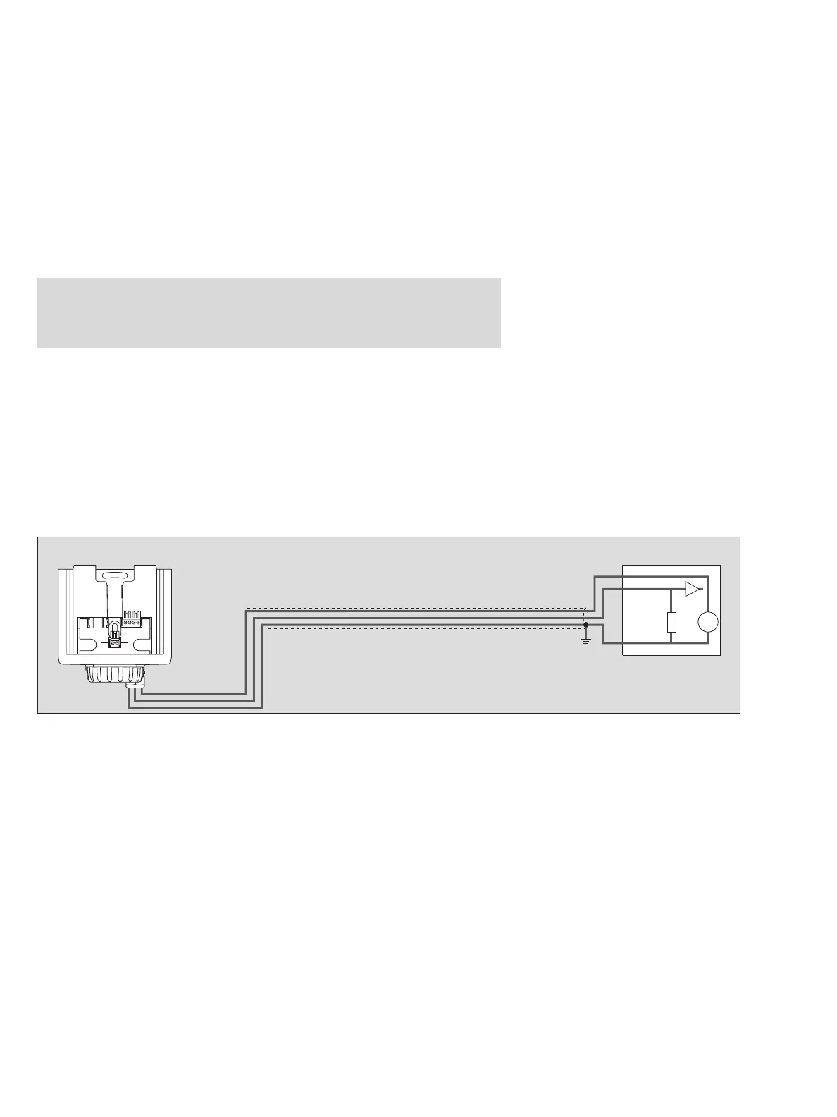
Installing the transmitter in non-explosion-hazard areas:
— When installing a transmitter in a non-explosion-hazard area, connect the cable
shield and the negative pole of the supply voltage to earth at the switch cabinet or
distribution panel.
— Ensure that the supply voltage provided by the control unit (ignoring the load re-
sistance) is at least as high as specified in the tables of page 19 to page 21.
— If digital communication in accordance with HART is to be used, the load resist-
ance of the supply unit must lie between 230 and 500 .
— The permissible cable lengths are shown in the tables on page 19 to page 21. In
each case, use the line marked "Number of transmitters = 1".
Caution:
Remove the explosion-protection markings from the transmitter. Once the
transmitter has been used after installation in this manner, it may never be
installed in explosion-hazard areas. Explosion hazard!
01223758_1_en.eps
Non-explosion-hazard area
Control unit
4 ... 20 mA
0 V
+
–
+