19
Electrical connections
Installing the transmitters in explosion-hazard areas of zone 2 or 22 without a
safety barrier
— Use only supply units of the device category 3.
● For safety reasons, we recommend that not more than 8 transmitters be connect-
ed to a 2-wire or 3-wire cable.
— Take care that the maximum permissible capacitance and inductance of connec-
tions to the supply unit are not exceeded, also taking the cable into account.
The safety-related input parameters of the transmitter are:
C
i
= 5 nF, L
i
= 50 μH.
Installing the transmitter in non-explosion-hazard areas:
● For safety reasons, we recommend that not more than 8 transmitters be connect-
ed to a 2-wire or 3-wire cable.
If the transmitters are equipped with relay or pump modules, not more than
4 transmitters should be connected to one cable.
The second cable gland is used for the cable to the next transmitter.
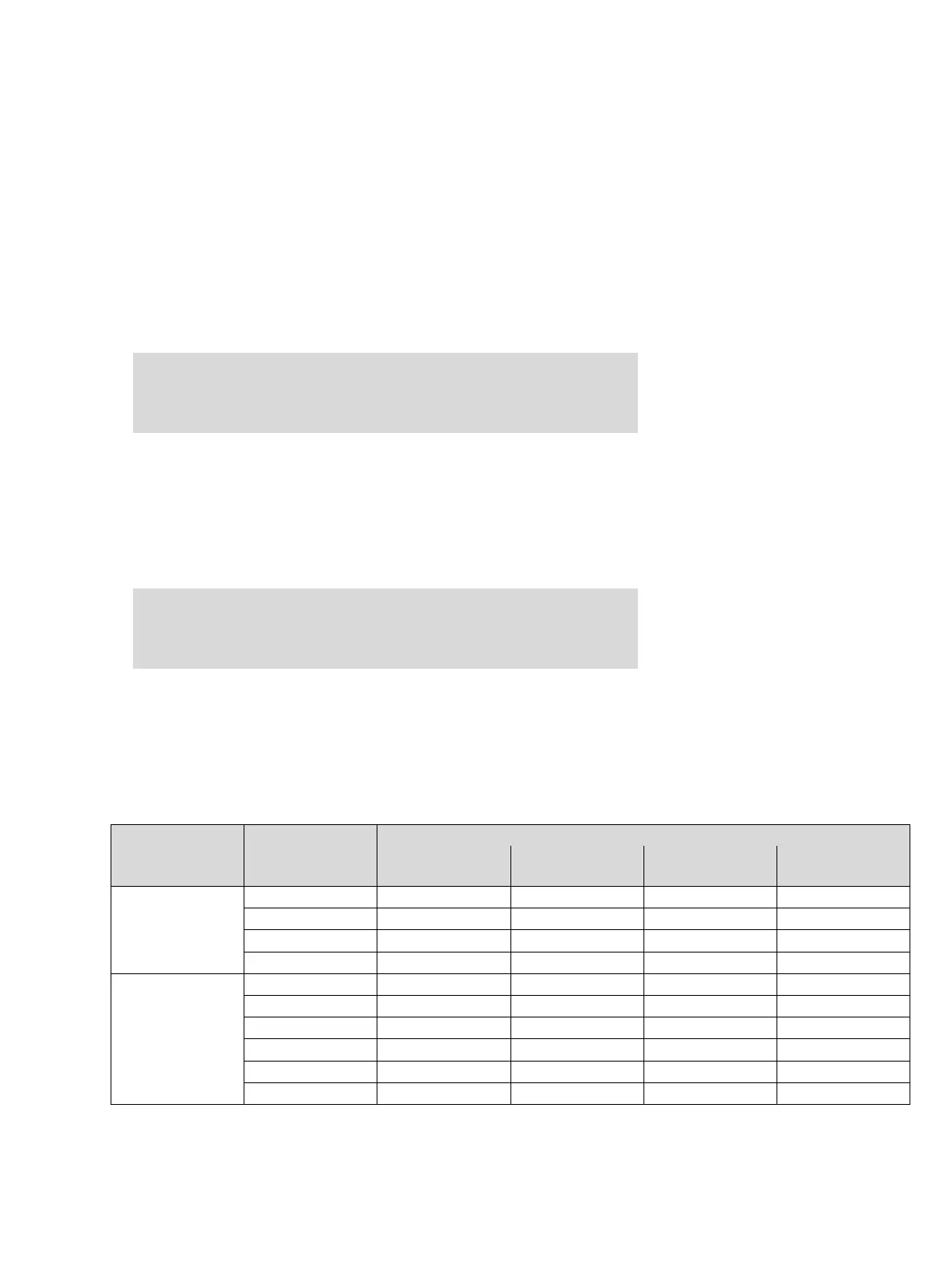
● The following tables show permissible combinations of transmitters, supply volt-
ages and maximum possible cable lengths.
— The capacitance values are typical values for commercially available shielded ca-
bles with PVC insulation. The use of cables with different capacity values will re-
sult in other cable lengths.
Transmitter without relay or pump module (2-wire):
Caution: The category 1 marking has to be cut out from the rating-plate
label. Once the unit has been used after installation in the above manner, it
may never be installed in explosion-hazard areas of zone 0 or zone 1
(device category 1 or 2). Explosion hazard!
Caution: The explosion-protection marking has to be removed from the
transmitter. Once the transmitter has been used after installation in this
manner, it may never be installed in explosion-hazard areas. Explosion haz-
ard!
Minimum
supply voltage
Number of transmit-
ters
Maximum cable length with a load resistance of 250
0.5 mm
2
265 pF/m
0.75 mm
2
320 pF/m
1.5 mm
2
375 pF/m
2.5 mm
2
400 pF/m
20 V
1 1042 m 921 m 828 m 792 m
2 1007 m 890 m 801 m 766 m
3 972 m 860 m 774 m 740 m
4 585 m 829 m 747 m 714 m
24 V
4 936 m 829 m 747 m 714 m
5 901 m 799 m 720 m 689 m
6 865 m 768 m 693 m 663 m
7 830 m 737 m 666 m 637 m
8 794 m 707 m 639 m 611 m
9 390 m 585 m 612 m 586 m