Installing accessories
32
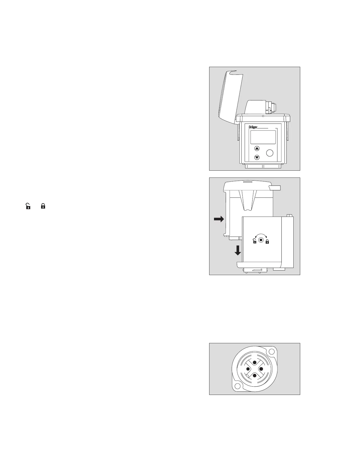
After connecting the relay module to the measuring unit:
6 Fit the cover again.
Mounting the measuring unit with relay module
7 Slide the measuring unit with relay module into the docking station and lower
it into position, see page 24.
8 Turn the eccentric catches clockwise with an Allen key to lock the measuring unit
(
⇒ = approx. 180
o
).
Connecting the devices to be switched
The relay module has three 3 potential-free outputs, each capable of switching
250 V / 5 A:
— A1 relay (switches when the A1 gas alarm is active)
— A2 relay (switches when the A2 gas alarm is active)
— Fault relay (switches in the case of a device fault)
Setting the alarm thresholds: see page 62.
● Connect the devices to be switched to the cable sockets.
Cable sockets of the following types may be used:
Pin assignments of the built-in plug on the relay module:
(see also the inside of the relay cover)
● Note the assignments of the relay outputs on the relay cover.
● Insert and lock the plug.
● Close the relay cover.
— Binder Type 692 Part No. 99–0210–00–04
— Amphenol Type C16-1 Part No. T 3109–001
— Hirschmann Type CA3 LD Part No. 934–125–100
— Dräger Safety Part No. 18 90 086
1 normally closed
2 common
3 normally open
4 not connected
03223758_1.eps
Polytron
OK
6
03323758_1.eps
7
8
1
2
3
4
04423758_1.eps