35
Installing accessories
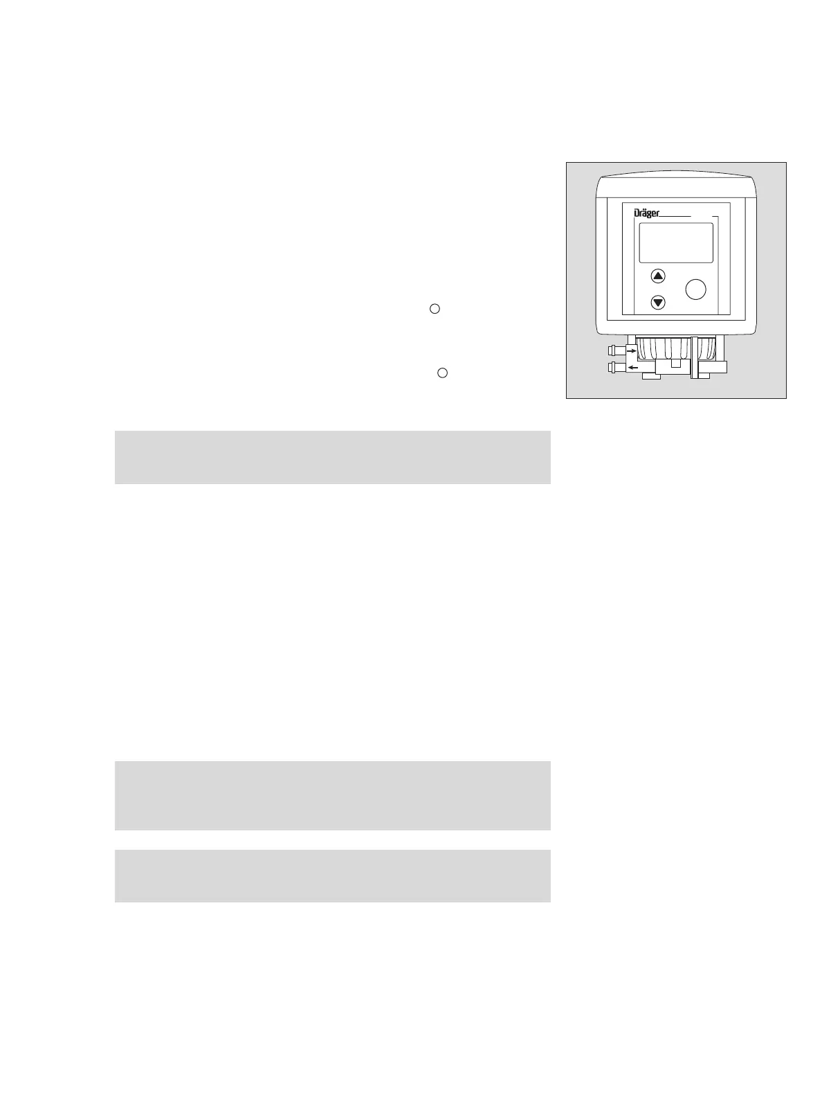
Installing the sensor and pump adapter
● Unscrew the bayonet ring from the transmitter and remove the blanking disc.
● Place the sensor in the opening with the Dräger logo facing the front, and push
upwards gently until the connector engages.
1 Place the fastening ring over the sensor opening.
2 Secure the sensor with the bayonet ring.
The assembly direction of the pump adapter is determined by the gas flow direction
between pump and sensor:
— Connectors for intake and exhaust air point to the left, the symbol is visible
from the front; the pump is positioned in front of the sensor in gas flow direction;
the sensor is positioned on the positive pressure side of the pump. This is the pre-
ferred operating mode for all sensors.
— Connectors for intake and exhaust air point to the right, the symbol is visible
from the front; the pump is positioned behind the sensor in gas flow direction; the
sensor is positioned on the negative pressure side of the pump. This operating
mode should only be selected for special reasons.
● Insert the pump adapter sleeves into the holes on the underside of the docking
station. The seal slides over the sensor.
1 Turn the securing ring clockwise until the pump adapter is secure.
Notes on installation of the inlet line
The material selected for the inlet hose or inlet pipe and the length of the inlet line
will affect the reaction time of the measured signal. In the worst cases, reactions with
the selected material, or absorption in this material, will prevent a measurable gas
concentration from reaching the sensor.
— Please contact your Dräger sales partner for choice on suitable selection of tub-
ing/hose.
— Maximum permissible pressure difference between flow inlet and the environment
of the transmitter: 50 mbar
— The pressure difference between the flow inlet and the environment of the trans-
mitter can cause an additional measurement error.
Note:
This operating mode is not permissible for DrägerSensor O
2
LS
(6809630) and DrägerSensor O
2
(6809720)!
Attention:
In order to check for leaks, we recommend that you measure the flow at
the inlet point and behind the transmitter before using the pump module
for the first time and every six months thereafter.
Attention:
Do not block the lower gas line of the pump adapter. This can damage the
gas sensor.
04123758_1.eps
1
Polytron
OK
+
2
+
–